
Schmitt Trigger
Procedure
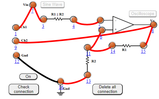
- Connect the components as mentioned below: L1-L7 or L1-L3 , L3-L7, L4-L5, L6-L11 or L6-L14, L8-L15, L12-L16, L8-L9, L13-L16, L14-L11.(For eg. click on 1 and then drag to 3 and so on.)
- Click on 'Check Connection' button to check the connections.
- If connected wrong, click on the wrong connection. Else click on 'Delete all connection' button to erase all the connections.
- Click on 'ON' button to start the experiment.
- Click on 'Sine Wave' button to generate input waveform (10 Vp-p, 1kHz)
- Click on 'Oscilloscope' button to get the output waveform.
- Vary the Amplitude, Frequency, volt/div using the controllers.
- Click on "Dual" button to observe both the waveform.
- Channel 1 shows the input sine waveform, Channel 2 shows the output square waveform.
- Click on "X-Y" button to observe the Hysteresis curve.
Note:
- The input sine wave is 10 Vp-p, 1kHz
- As, volt/div is set to 1 volt/div. As the Volts/Div is too low, you’ll clip the signal. So, change the volt/div and set to 5 volt/div. Which implies each mazor division is 5 volt where as each minor division is 1volt.
- Click on oscilloscope. This will give square wave.
- As, volt/div is set to 1 volt/div. As the Volts/Div is too low, you’ll clip the signal. So, change the volt/div and set to 5 volt/div. Which implies each mazor division is 5 volt where as each minor division is 1volt.
- Click on "Channel 1" or "Channel 2" button to observe either the input waveform or output waveform.
- Click on "Dual" button to observe both the waveform
- Click on "X-Y" button to observe the Hysteresis curve. (X-Y mode is a specialized two-channel mode of oscilloscopes when the signal of channel 1 is used for the deviation along the horizontal axis (X) and the signal of channel 2 – along the vertical axis (Y).)