
To Measure the Scattering Parameters of Circulator.
Introduction
A circulator is a device that transports radio frequency or microwave signals from one port to another. They typically have three ports. They are made of magnets and ferrite materials with magnetic properties. Circulators can be made to circulate clockwise or counterclockwise. So the name "circulator" makes sense in that it transmits the signal around to the three ports. These devices are also referred to as duplexers because they allow the transmission of two signals over one channel. This allows a receiver and a transmitter to share the same antenna. This is the most common use for a circulator. When the transmitter sends a signal, the device directs the signal to the antenna port. So in summary, a circulator is a device that is designed to direct radio frequencies or microwave signals from Port 1 to Port 2 with a minimum loss. Following is the basic parameters of circulator for study.
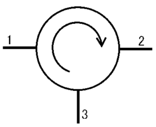
Fig. 1 Circulator
- The coupling factor is defined as:
- It is the ratio of power fed to input arm to the input power detected at not coupled port with other port terminated in the matched load.
Hence--------------------(2)
Component List
Microwave Supply
Provides the necessary microwave power to the circulator, enabling the operation and measurement of the signals at different ports.Isolator
Prevents reflected signals from returning to the microwave source, protecting it from potential damage and ensuring stable operation by allowing unidirectional signal flow.Frequency Meter
Measures the frequency of the microwave signals being transmitted through the circulator, ensuring accurate characterization and tuning during tests.Variable Attenuator
Allows for precise control of the signal power entering the circulator, enabling adjustments to analyze the effects of varying input power on isolation and coupling.Slotted Line
A measurement tool used to visualize standing wave patterns and measure voltage standing wave ratio (VSWR) along the transmission line, aiding in the assessment of signal behavior.Detector Mount
Holds the detector that measures the output signal power from the circulator, providing data necessary for calculating the isolation and coupling factors.Cathode Ray Oscilloscope (CRO)
Visualizes the output signal waveforms, allowing for analysis of amplitude, frequency, and phase relationships, which is crucial for evaluating the performance of the circulator.3-Port Circulator
A non-reciprocal microwave device that routes signals from one port to another while preventing backflow. It is essential for measuring isolation (how much signal is prevented from going back to the input) and coupling factor (how much power is transferred to the other ports).Matched Terminal
Absorbs excess microwave power at one of the ports, preventing reflections and ensuring that the measurements of isolation and coupling factors are accurate by maintaining proper impedance matching.
Block Diagram
For V1 Voltage:
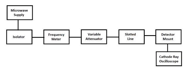
Fig. 2 Bench setup for V1 Voltage
For V2 Voltage:
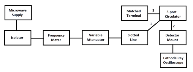
Fig. 3 Bench setup for V2 Voltage
For V3 Voltage:
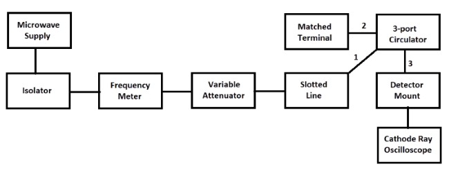
Fig. 4 Bench setup for V3 Voltage