
Detection of SA0 faults on a VLSI circuit for 4-input Priority Encoder circuit
Introduction
Encoders are devices that convert one of a maximum of 2n decimal input lines to an n bit binary output. This is because 2n different values can be translated to an n bit binary code. Priority encoder is an enhanced version of encoder that takes care of the case where multiple inputs are high at the same time. It is done by prioritizing certain input lines over the other, such that there is a precedence for the input lines. Now, if there are multiple high inputs, only the one occurring higher in the priority will be considered for conversion to binary.
4-input Priority Encoder
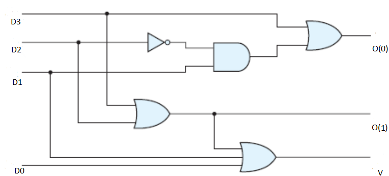
A 4-input Priority Encoder takes one of 4 inputs and produces 2 outputs corresponding to the binary equivalent of the line selected. Its circuit diagram is shown below where D0, D1, D2 and D3 are the input lines, and O(1) and O(0) are the output lines corresponding to the given input. Here O(1) and O(0) correspond to the binary bits of the binary number generated by the priority encoder. E.g For the binary number 01, O(1) = 0 and O(0) = 1. We also have an additional output V that becomes high only if at least one of the input lines is high i.e. checks whether none of the input lines are high or not.
Truth Table
In this circuit, our priority order is D3, D2, D1, D0. So if D3 is high, then whatever be the value of D2, D1 and D0, O(0) and O(1) will output high. Similarly if D3 is low and D2 is high, then O(1) is high and O(0) is low. If D3 and D2 are low, and D1 is high, O(1) is low and O(0) is high. When D3, D2 and D1 are low, and D0 is high, O(0) and O(1) are both low. In all these cases, V is high and becomes low only if all of the inputs are low simultaneously. This is summarized in the form of the truth table given below.
| D3 | D2 | D1 | D0 | O(1) | O(0) | V |
|---|---|---|---|---|---|---|
| 1 | X | X | X | 1 | 1 | 1 |
| 0 | 1 | X | X | 1 | 0 | 1 |
| 0 | 0 | 1 | X | 0 | 1 | 1 |
| 0 | 0 | 0 | 1 | 0 | 0 | 1 |
| 0 | 0 | 0 | 0 | 0 | 0 | 0 |
Table 1: Truth Table of Priority Encoder
From the truth table, we find the boolean expression for the output variables O(1), O(0) and V as follows:
O(0)=D3+D2'D1
O(1)=D3+D2
V=D3+D2+D1+D0
Stuck at Faults
A stuck-at fault (SAF) is used to mimic a manufacturing defect in circuits and devices. It causes the logic signal on a wire to be tied at 1 or 0, for stuck-at-1 (SA1) and stuck-at-0 (SA0) respectively no matter its previous value. This helps us to detect manufacturing defects showing similar kinds of behavior. The simulator is designed to cover SA0 faults at multiple points on different wires.
The input combinations given below along with the positions where the fault is detected give us the corresponding faulty outputs: O(1)f, O(0)f and Vf
| D3 | D2 | D1 | D0 | Fault | O(1) | O(0) | V | O(1)f | O(0)f | Vf |
|---|---|---|---|---|---|---|---|---|---|---|
| 0 | 1 | 1 | 0 | SA0 fault at D2 | 1 | 0 | 1 | 0 | 1 | 1 |
| 1 | 0 | 0 | 1 | SA0 fault at D0 | 1 | 1 | 1 | 1 | 1 | 1 |
| 0 | 0 | 1 | 1 | SA0 fault at D1, O(0) | 0 | 1 | 1 | 0 | 0 | 1 |