
Ripple and Synchronous counters 
Procedure
Ripple (Asynchronous Counter)
To design a ripple counter, we should first design a J-K Flip Flop. To design a J-K flip flop, we have to first design a 3 input NAND gate and a LATCH. We have designed 3 input NAND gate and LATCH as below and packaged them into components.
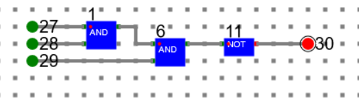
3-IN-NAND (27, 28, 29: inputs. 30: Output)
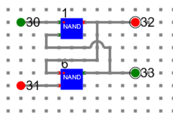
LATCH
Using the 3-In-NAND and LATCH, we have designed J-K-FlipFlop as below. Then packaged it into component.
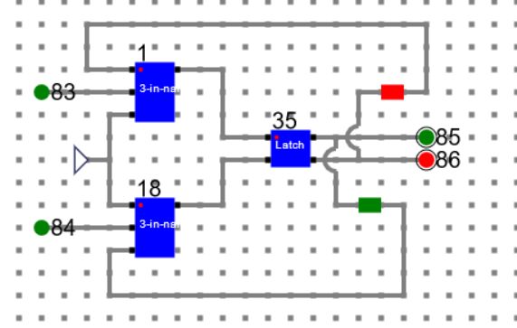
J-K-FlipFLop (83, 84: Inputs. 85, 86: Outputs)
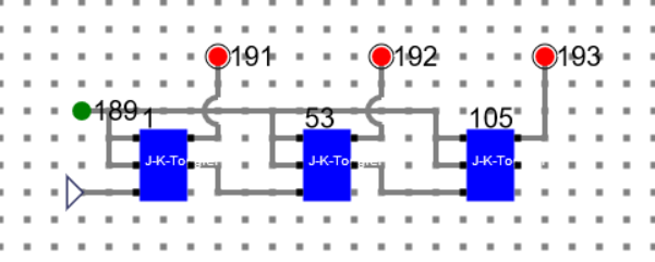
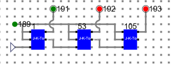
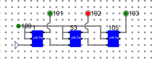
Now using the J-K-FlipFLop, we have designed the ripple counter as below.
3 Bit Ripple Counter
LSB: 191 MSB: 193
Clock 1:
Number: 000
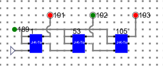
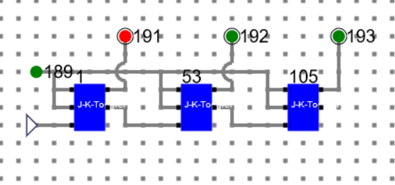
Clock 2:
Number: 001
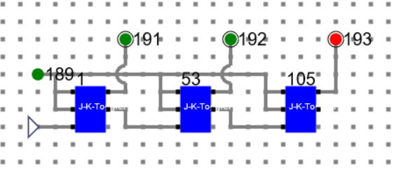
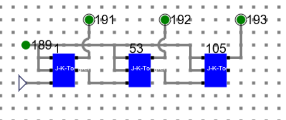
Clock 3:
Number: 010
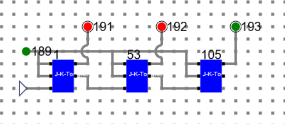
Clock 4:
Number: 011
Clock 5:
Number: 100
Clock 6:
Number: 101
Clock 7:
Number: 110
Clock 8:
Number: 111
Clock 9: (Back to initial state)

Number: 000
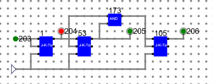
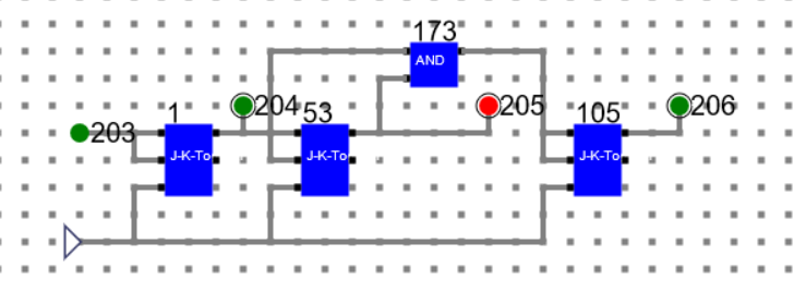
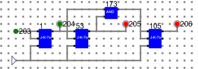
3-Bit synchronous Counter
Using J-K-FlipFlop and AND gate we can design asynchronous counters as below.
204: LSB, 206: MSB
Clock 1:

Number: 111
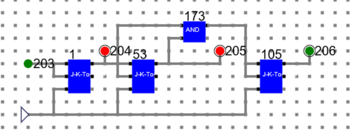
Clock 2:
Number: 110
Clock 3:
Number: 101
Clock 4:
Number: 100
Clock 5:
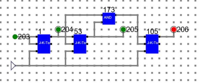
Number: 011
Clock 6:
Number: 010
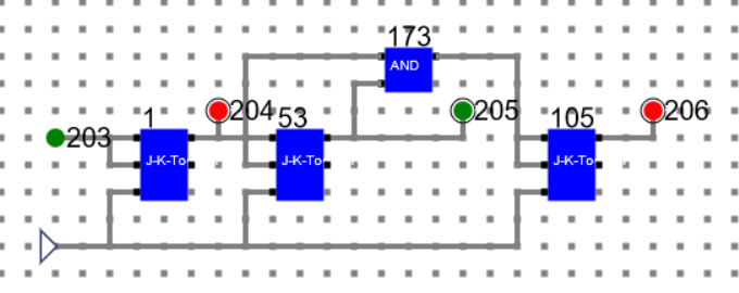
Clock 7:
Number: 001
Clock 8:
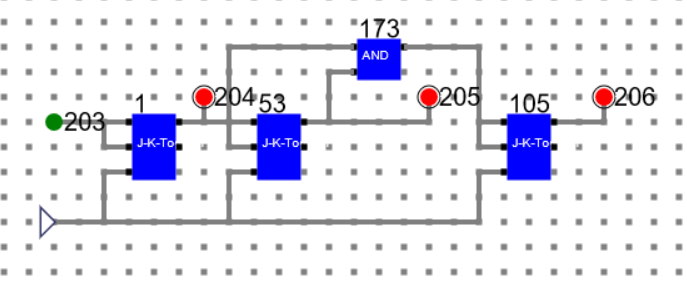
Number: 000
Clock 9: (Back to initial state)
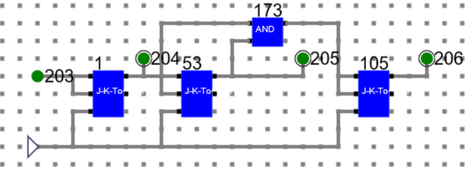
Number: 111
Manual
- Follow the below manual and perform the experiment
- Manual --> Click Here