
Ring Rolling process
Theory
Ring rolling is a specialized type of metal forming operation, which reduces the thickness (cross section) and enlarges the diameter (circumference) of the work piece by a squeezing action as it passes between two rotating rolls. The ring rolling process is widely used to produce seamless rings with outer diameters ranging from 100 millimetres up to 8 meters using cold or hot work pieces.
These rings are commonly used as flanges, pipe flanges, ring gears, structural rings, gas-turbine rings, etc. Titanium and super alloy rings are used as housing parts for jet engines in the aerospace industry.
Advantages of the process include uniform quality, smooth surface finish, close tolerance, short production time, and relatively small material loss. However, ring rolling is poor in adequate filling of roll cavities when they are too deep, as material tends to expand in diameter instead of filling the cavities.
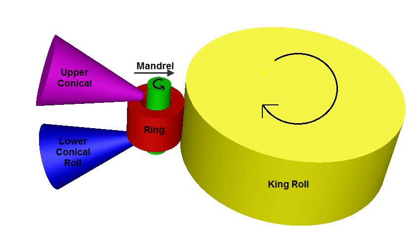
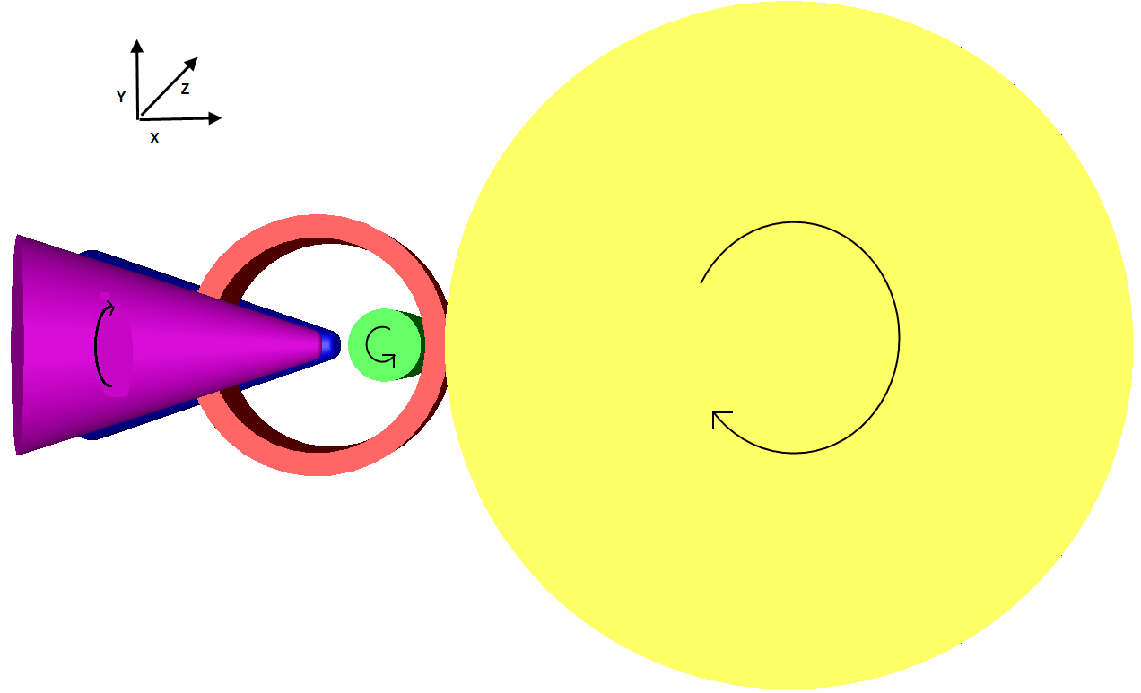
Figure: (a) 3-D View of Ring Rolling Process, (b) Schematic View of Ring Rolling Process
Ring Rolling Process Description
A typical ring rolling process consists of two sets of rolls: a radial set that reduces the radial thickness of the ring and an axial set that controls the width of the ring.
The main deformation occurs between the king (main) roll and the mandrel (pressure) roll. The rotation of the king roll drives the ring through friction at the roll–ring interface, causing a continuous reduction in wall thickness while the ring diameter increases due to material incompressibility.
Types of Ring Rolling Process
Cold Ring Rolling
Cold rolling significantly increases the yield strength of steel by strain hardening. Yield stress enhancement of approximately 15%–30% is observed, especially in high-strain zones.
- Close dimensional tolerances
- Repeatable cross-sectional shapes
- Capability to produce long sections
- Improved corrosion resistance with coated metals
Analytical Description of Ring Rolling
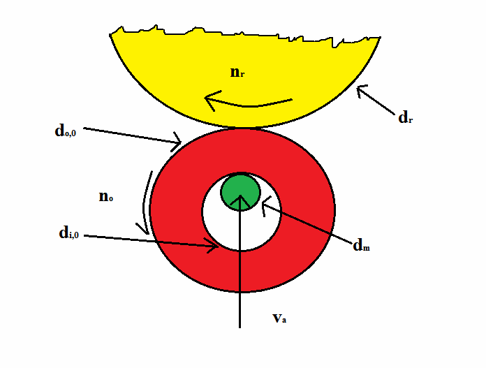
Process Parameters
- di – Inner diameter
- do – Outer diameter
- dr – King roll diameter
- dm – Mandrel diameter
- nr – Roller rotational speed
- no – Ring rotational speed
- va – Mandrel advance velocity
Volume Conservation
Assuming plane strain conditions:
(π/4)(do2 − di2)w = (π/4)(do,02 − di,02)w
Equivalent Flat Rolling Diameter
King Roll
Mandrel Roll
Mandrel Advance Velocity
Roll Bite Condition
μ > tan α
Maximum Draft and Mandrel Velocity
Thus, the mandrel advance velocity must be controlled within this limit to ensure continuous rotation of the ring during the rolling process.