
To Plot the Radiation Pattern and Determining Gain of a Pyramidal Horn Antenna.
Procedure
Instructions to Record the Value for Transmitting Voltage
Step-1: Click on Components button for components to pop up.
Step-2: Click on the "Components", drag them to the test bench and place them as shown in fig. 1.
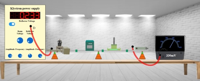
Fig. 1 Setup for recording the value for transmitting voltage
Step-3: After placing the components on the test bench, connect the wires accordingly.
Step-4: If your connections are correct then you may continue to take down the readings, if not then click on "Reset Button" and try it again.
Step-5: Move the "Beam Voltage" knob and set it to 250 or above to record your readings.
Step-6: Toggle the switch button and move the "Reflector Voltage" knob to set the reflector voltage to maximum negative value.
Step-7: As soon as you start varying the reflector voltage you will observe a voltage value on millivoltmeter.
Step-8: Keep varying the "Reflector voltage" till you get maximum voltage at millivoltmeter (You will get maximum voltage value at values between 232 and 240 of voltage).
Step-9: Note down the value for Transmitting Voltage from millivoltmeter
Step-10: Click on "Add to table" button to record the readings for Output Voltage, Beam Voltage and Reflector Voltage.
Step-12: Click on "Print" button to print your current page (readings and connections) or to save your page (readings and connections) in a PDF form. After clicking on "Print Button" set the layout as "Landscape" to get a proper view of the page then go to more settings and click on the checkbox named "Background graphics".
Step-13: Click on "Next" button to calculate gain and to plot radiation pattern of Horn Antenna.
Instructions to Record the Value for Gain and Plot the Radiation Pattern for Horn Antenna
Step-1: Click on Components button for components to pop up.
Step-2: Click on the "Components", drag them to the test bench and place them as shown in fig. 2.
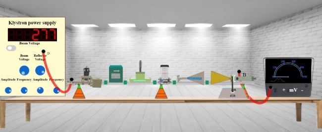
Fig. 2 Setup for recording the Value for gain and plot the radiation pattern for horn antenna
Step-3: After placing the components on the test bench, connect the wires accordingly.
Step-4: If your connections are correct then you may continue to take down the readings, if not then click on "Reset Button" and try it again.
Step-5: Once you're done with the connections, you'll notice voltage for Horn Antenna at 0 degree on millivoltmeter.
Step-6: Note down that value for Receiving voltage and click on "Calculate" button to calculate gain at that particular degree.
Step-7: Click on Add to table to take down the values of Gain on that particular degree.
Step-8: Now click on "+" button and Repeat the process for 10 to 90 degree (for anticlockwise direction) as you did for the first reading.
Step-9: Or click on "-" button and Repeat the process for 360 to 270 degree (for clockwise direction) as you did for the first reading.
Step-10: Note down all the readings for anticlockwise direction (0 to 90 degree) as well as for clockwise direction (360 to 270 degree).
Step-11: Click on "Print" button to get your page (readings and connections) in a PDF form.
Step-12: Click on "Plot" button to plot a graph as per your readings.
Step-13: If you want to save the graph click on the camera icon just above the graph.