Pulse-width Modulation (PWM)
Pulse-width modulation (PWM), or pulse-duration modulation (PDM), is a method of controlling the average power delivered by an electrical signal.
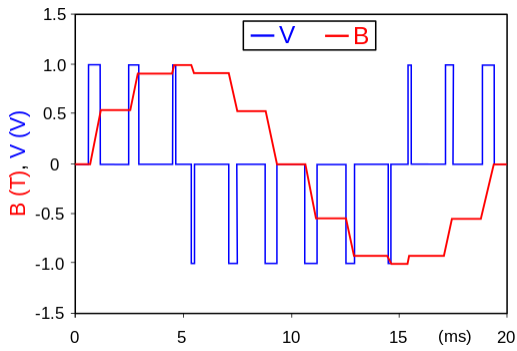
Fig: An example of PWM in an idealized inductor driven by a blue line voltage source modulated as a series of pulses, resulting in a red line sine-like current in the inductor. The rectangular voltage pulses nonetheless result in a more and more smooth current waveform, as the switching frequency increases. The current waveform is the integral of the voltage waveform.
Duty cycle
A low duty cycle equates to low power because the power is off for most of the time; the word duty cycle reflects the ratio of "on" time to the regular interval or "period" of time. The duty cycle is measured in percent, with 100% representing full on. A digital signal has a duty cycle of 50% and looks like a "square" wave when it is on 50% of the time and off the other 50%. A digital signal has a duty cycle of greater than 50% when it spends more time in the on state than the off state. A digital signal has a duty cycle of 50% when it alternates between the on and off states more often than not.
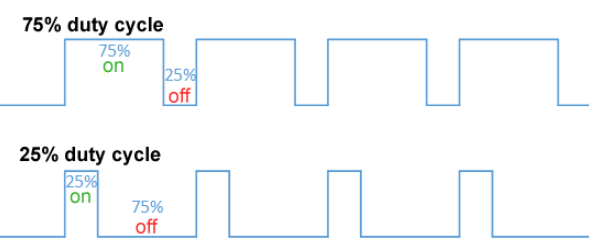

Fig: Duty cycle of 75%, 25%, and 50%
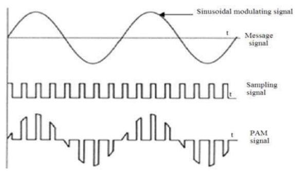
Fig: Pulse Amplitude Modulation Signal
Mathematical Formulation of pulse-width waveform
Pulse-width modulation uses a rectangular pulse wave whose pulse width is modulated resulting in the variation of the average value of the waveform. If we consider a pulse waveform f(t), with period T, low-value ymin, a high-value ymax, and a duty cycle D, the average value of the waveform is given by
\(\bar{y} = \frac{1}{T} \int_0^t f(t) \, dt\)
\(\bar{y} = \frac{1}{T} \left( \int_0^{DT} y_{\text{max}} \, dt + \int_{DT}^T y_{\text{min}} \, dt \right)\)
\(= \frac{1}{T} \left( D \cdot T \cdot y_{\text{max}} + T(1 - D) \cdot y_{\text{min}} \right)\)
\(= D \cdot y_{\text{max}} + (1 - D) \cdot y_{\text{min}}\)
From this, the average value of the signal (y ̅) is directly
dependent on the duty cycle D.
The simplest way to generate a PWM signal is the intersection
method, which requires only a sawtooth or a triangle waveform
(easily generated using a simple oscillator) and a comparator. When
the value of the reference signal is more than the modulation
waveform, the PWM signal (magenta) is in the high state, otherwise,
it is in the low state.
Generation of PWM and PPM Signals
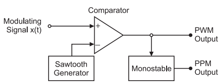
Fig: PWM and PPM Generator
(i) A sawtooth generator generates a sawtooth signal of frequency
fs, and this sawtooth signal in this case is used as a sampling
signal.
(ii) It is applied to the inverting terminal of a comparator.
(iii) The modulating signal x (t) is applied to the non-inverting
terminal of the same comparator.
(iv) The comparator output will remain high as long as the
instantaneous amplitude of x (t) is higher than that of the ramp
signal.
(v) This gives rise to a PWM signal at the comparator output as
shown in the figure below
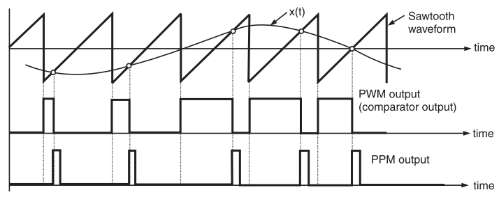
Fig: PWM and PPM Modulation
Here, it may be noted that the leading edges of the PWM waveform
coincide with the falling edges of the ramp signal. Thus, the
leading edges of the PWM signal are always generated at fixed time
instants.
However, the occurrence of its trailing edges will be dependent on
the instantaneous amplitude of x(t). Therefore, this PWM signal is
said to be trail edge modulated PWM.
Demodulation of PWM Signal

Fig: Schematic diagram of Pulse Width Modulation
PWM signal must first be converted to a pulse-amplitude modulation
(PAM) signal and then passed through a low-pass filter. The PWM
signal is applied to an integrator and hold circuit. When the
positive edge of pulse appears, the integrator generates ramp output
whose magnitude is proportional to the pulse width. After the
negative edge, the hold circuit maintains the peak ramp voltage for
a given period and then forces the output voltage to zero.
The waveform is the sum of a sequence of constant-amplitude and
constant-width pulse generated by demodulator. This signal is then
applied to the input of clipping circuit, which cuts off the portion
of signal below the threshold voltage and outputs the reminder.
Therefore the output of clipping circuit is a PAM signal whose
amplitude is proportional to the width of PWM signal. Finally, the
PAM signal passes through a simple low-pass filter and the original
audio signal is obtained.
Effect of Distortion on pulse width modulation
Distortion for a PWM waveform is a direct function of the transmission channel. For a given step function, the rise time of the pulse edge will increase as the cable length increases. Since a pulse is composed of several harmonics of sine functions, the high-frequency components of the pulse will have the highest susceptibility to attenuation and delay. If the frequency of the transmission exceeds the bandwidth of the channel, significant distortion will occur.
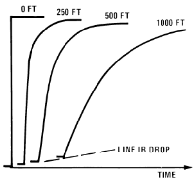
Fig: Example of Distortion of a Pulse Edge with Increased Cable Length
Effect of noise on pulse width modulation
Like frequency modulation, PWM has inherent noise immunity that permits an analog signal to be sent on a relatively lengthy wire-line communication channel with minimal interference. The amplitude assumes one of two relatively discrete values similar to digital communication; thereby the noise has to be significant enough to change the switching of the states. However, as the length of the transmission channel increases, the probability of outside interference affecting the signal integrity also increases. Noise and distortion can compromise the function of PWM by skewing the duty cycle and altering the wave shape of the pulse.
Applications
Pulse-width modulation (PWM), or pulse-duration modulation (PDM), is
a method of controlling the average power delivered by an electrical
signal.
For telecommunication purposes, the utility of pulse width
modulation (PWM) lies within the duty cycle of the encoded signal.
Like frequency modulation, PWM has inherent noise immunity that
permits an analog signal to be sent on a relatively lengthy
wire-line communication channel with minimal interference
