Pulse-position modulation (PPM)
Pulse-position modulation (PPM) is a form of signal modulation in
which M message bits are encoded by transmitting a single pulse in
one of 2M possible required time shifts. This is repeated every T
seconds, such that the transmitted bit rate is M/T bits per second.
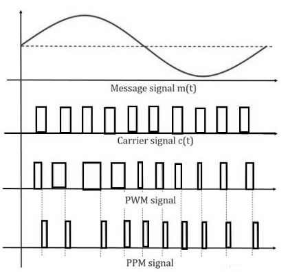
Pulse position modulation is one type of analog modulation which
allows variation within the position of the pulses based on the
sampled modulating signal’s amplitude is called PPM or Pulse
Position Modulation. In this type of modulation, the amplitude &
width of the pulses are kept stable & the position of the pulses
only varied.
The PPM technique allows computers to transmit data by simply
measuring the time taken to reach each data packet to the computer.
So is frequently used within optical communication where there is
small multi-pathway interference. This modulation totally transmits
digital signals & cannot be utilized by analog systems. It transmits
simple data which is not efficient while transferring files.

Fig: PPM Waveforms
Demodulation of PPM Signal

The noise corrupted PPM waveform is received by the PPM demodulator circuit. The pulse generator develops a pulsed waveform at its output of fixed duration and applies these pulses to the reset pin (R) of a SR flip-flop. A fixed period reference pulse is generated from the incoming PPM waveform and the SR flip-flop is set by the reference pulses. Due to the set and reset signals applied to the flip-flop, we get a PWM signal at its output. The PWM signal can be demodulated using the PWM demodulator.
Effect of noise on pulse position modulation
Since in a PPM system the transmitted information is contained in
the relative positions of the modulated pulses, the presence of
additive noise affects the performance of such a system by
falsifying the time at which the modulated pulses are judged to
occur. Immunity to noise can be established by making the pulse
build up too rapidly that the time interval during which noise can
exert any perturbation is very short. Indeed, additive noise would
have no effect on the pulse positions if the received pulses were
perfectly rectangular, because the presence of noise introduces only
vertical perturbations. However, the reception of perfectly
rectangular pulses would require an infinite channel bandwidth, and
the received pulses have a finite rise time, so the performance of
the PPM receiver is affected by noise, which is to be expected.
As in a continuous wave (CW) modulation system, the noise
performance of a PPM system may be described in terms of the output
signal-to-noise ratio (SNR). Also, to find the noise improvement
produced by PPM over baseband transmission of a message signal, we
may use the figure of merit defined as the output signal-to-noise
ratio of the PPM system divided by the channel signal-to-noise
ratio. Assuming that the average power of the channel noise is small
as compared to the peak pulse power, the figure of merit of the PPM
system is proportional to the square of the transmission bandwidth
of the (say, BT) normalized with respect to the message signal
bandwidth (say, W). When, however, the input signal-to-noise ratio
drops below a critical value, the system suffers a loss of the
wanted message signal at the receiver output. That is a PPM system
suffers from a threshold effect of its own.
Delta Modulation
DM is the simplest form of differential pulse-code modulation (DPCM). The encoder performs the function of differentiation; a quantizer precedes the differencing of adjacent quantized samples; the decoder is an accumulator, which if correctly initialized exactly recovers the quantized signal. In this technique, the difference between successive samples is encoded into n-bit data streams. In delta modulation, the transmitted data are reduced to a 1-bit data stream. It uses the simplest possible quantizer i.e. two-level or one-bit quantizer.
Generation of Delta Modulated Signal

Fig: Delta Modulation and Demodulation
DPCM is much simpler if we just use the previous sample for the predictor. The predictor is just a delay. In delta modulation, the transmitted data are reduced to a 1-bit data stream. It uses the simplest possible quantizer i.e. two-level or one-bit quantizer.

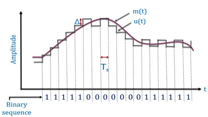
Fig: Waveform representation of delta modulation where m(t) is the analog signal and u(t) is the staircase function.
Here, the present sample value is compared with the previous sample value and this result whether the amplitude is increased or decreased is transmitted. If the difference is positive then the approximated signal is increased by one step i.e. ′∆′ and ‘1’ is transmitted. If the difference is negative then the approximated signal is reduced by ′∆′ and ‘0’ is transmitted as shown in the figure. Since the delta modulation transmits only one bit per sample. Therefore, the signalling rate and transmission bandwidth is quite small for delta modulation as compared to PCM and DPCM.
Effects of noise on delta modulation or drawbacks of delta modulation
There are two kinds of quantization errors or noises that are present in delta modulation. They are 1. Granular noiseand 2. Slope Overload Distortion.
1. Granular noise

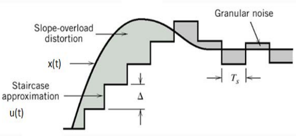
Fig: Delta Modulation where x(t) is the analog signal and u(t) is the staircase function.
Granular or Idle noise occurs when the step size is too large compared to a small variation in the input signal. This means that for very small variations in the input signal, the staircase signal is changed by a large amount (Δ) because of the large step size. The figure shows that when the input signal is almost flat, the staircase signal u(t) keeps on oscillating by ±Δ around the signal. The error between the input and approximated signal is called granular noise. The solution to this problem is to make the step size small.
2. Slope Overload Distortion
Slope overload distortion occurs due to the large dynamic range of the input signal. In the above figure, the rate of rise of input signal x(t) is so high that the staircase signal cannot approximate it, the step size delta becomes too small for staircase signal u(t) to follow the step segment of x(t). Hence, there is a large error between the staircase approximated signal and the original input signal x(t). This error or noise is known as slope overload distortion.
Applications
The Delta Modulation method is generally used for the encoding of signals from analog to PCM. It is also applied for signal conversion in television systems. One of the most critical applications of this technique is that it is used for real-time Signal Processing
