Pulse Code Modulation (PCM)
Starting in the 1920s, long-distance telephone links used frequency
division multiplexing. A cable with a bandwidth of 3 MHz can support
(in principle) 1000 3 kHz voice channels. But 1000 filters,
modulators, and demodulators are needed.
Using PCM, multiple connections could be time division multiplexed
(TDM). The Bell System settled on 1.544 Mbit/s (by experimentation).
8000 • (24 • 8 + 1) = 8000 • 193 = 1544000
Where the number of frames per second is 8000 and 24 8bit channels
plus 1 framing bit.
This TDM signal is called digital signal level 1 (DS1).
This 24 to 1 digital multiplexing technique was used for the T1
carrier system for voice communication.
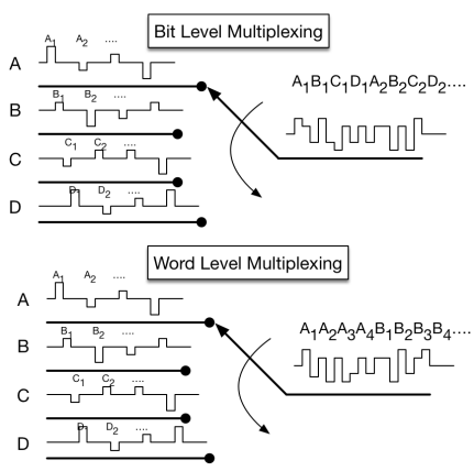
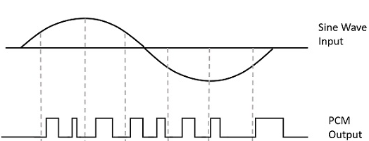
Fig: PCM waveform
Instead of a pulse train, PCM produces a series of numbers or digits, and hence this process is called as digital. Each one of these digits, though in binary code, represent the approximate amplitude of the signal sample at that instant.
Bit rate and bandwidth requirements of PCM
• The bit rate of a PCM signal can be calculated form the number of
bits per sample × the sampling rate. Bit rate =𝑛𝑏×𝑓𝑠. The bandwidth
required to transmit this signal depends on the type of line
encoding used.
• A digitized signal will always need more bandwidth than the
original analog signal. Price we pay for robustness and other
features of digital transmission.
Linear Pulse Code Modulation (LPCM)
Pulse-code modulation (PCM) is a multiplexing technique used to digitally represent sampled analog signals. Linear pulse-code modulation (LPCM) is a specific type of PCM in which the quantization levels are linearly uniform.
Differential Pulse Code Modulation (DPCM)
The encoder performs the function of differentiation; a quantizer
precedes the differencing of adjacent quantized samples; the decoder
is an accumulator, which if correctly initialized exactly recovers
the quantized signal.
DPCM takes the values of two consecutive samples; if they are analog
samples, quantize them; calculate the difference between the first
one and the next; the output is the difference.
For example, m[k] is the sampled unquantized signal we want to
transmit, and mq[k] is the quantized signal. m^[k] is the prediction
of m[k] based on previous samples mq[k]. d[k] = m[k] − mˆ [k], the
unquantized difference between m[k] and the prediction. dq[k] is the
actual quantized difference that will be transmitted. A predictor
will take previous samples of the signal, and compute the next
expected sample.
At the receiver side, the input is quantized difference signal
dq[k]. The receiver will produce previous values of mq[k]. Then the
predictor computes mq^[k], the next predicted sample. Then dq[k] is
added to the predicted signal mq^[k] to recover the transmitted
signal.
Basic Elements of PCM
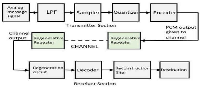
Fig: Pulse Code Modulation
Pulse Code Modulation
The transmitter section of a Pulse Code Modulator circuit consists of Sampling, Quantizing and Encoding, which are performed in the analog-to-digital converter section. The low pass filter prior to sampling prevents aliasing of the message signal. The construction filter helps to obtain the original signal. The signal strength can be enhanced through this regenerative repeater. So, the channel’s output also includes a regenerative repeater circuit to balance the signal loss, renovate the signal & also increases the signal strength.
Pulse Code Demodulation
Pulse Code Demodulation will be doing the same modulation process in
reverse. Demodulation starts with the decoding process, during
transmission the PCM signal will be affected by noise interference.
So, before the PCM signal sends to the PCM demodulator, we have to
recover the signal to the original level for that we are using a
comparator. The PCM signal is a series pulse wave signal, but for
demodulation, we need a wave to be parallel.
By using a serial to parallel converter the series pulse wave signal
will be converted into a parallel digital signal. After that the
signal will pass through the n-bits decoder, it should be a Digital
to Analog converter. Decoder recovers the original quantization
values of the digital signal. This quantization value also includes
a lot of high-frequency harmonics with original audio signals. For
avoiding unnecessary signals we utilize a low-pass filter at the
final part.
Quantization Process:
A continuous signal, such as voice, has a continuous range of amplitudes and therefore its samples have a continuous amplitude range. In other words, within the finite amplitude range of the signal, we find an infinite number of amplitude levels. It is not necessary in fact to transmit the exact amplitudes of the samples. Any human sense (the ear or the eye), as an ultimate receiver, can detect only finite intensity differences. This means the original continuous signal may be approximated by a

Fig: Description of a memoryless quantizer
signal constructed of discrete amplitudes selected on a minimum error basis from an available set. For example, amplitude quantization is defined as the process of transforming the sample amplitude m(nTs) of a message signal m(t) at time t = nTs into a discrete amplitude v(nTs) taken from finite set of possible amplitudes.
Quantization Noise in PCM:
It is the type of quantization error, which usually occurs in analog
to digital converter. For example, in music, the signals keep
changing continuously, where regularity is not found in errors. Such
errors create a wideband noise called Quantization Noise.
Quantization approximates the sampled value to the nearest discrete
value from the set of finite discrete levels. Quantizers are of two
types.
1. Mid-treed quantizer
2. Mid-rise quantizer
Quantizing step size, Δ=(xmax-xmin)/q
Q=number of quantized level
Δ=(xmax-xmin)/2n
Where n is the number of bits used to represent each level
1. Mid-treed quantizer
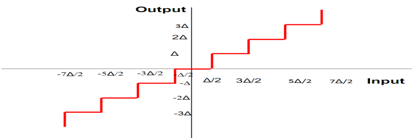
Error is ± Δ/2
Quantization error=quantized value-actual sampled value
Qe=xq(nTs)-x(nTs).
In mid treed quantization the input values lies between ± Δ/2, ±
3Δ/2, ± 5Δ/2, . . . in that output values are quantized values at ±
Δ,± 2Δ,±3Δ,……. Suppose the input (i.e. sampled value) lies between ±
Δ/2 which is approximated as zero. If the input values lie between
Δ/2 to 3Δ/2 this quantizer approximates sampled value as Δ. Here the
origin of the treed of staircase lies at the midpoint so the name is
called mid treed quantizer. In that maximum quantization error is
Δ/2 and the minimum quantization error is -Δ/2.
2. Mid-Rise Quantizer:-
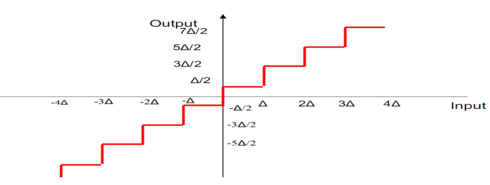
Fig: Mid-Rise Quantizer
In mid-rise quantizer the input values are ± Δ,± 2Δ,± 3Δ,….. the quantized values are ± Δ/2, ± 3Δ/2, ± 5Δ/2,…. The quantization error is ± Δ/2
Companding in PCM Systems
The word Companding is a combination of Compressing and Expanding, which means that it does both. This non-linear technique is used in PCM which compresses the data at the transmitter and expands the same data at the receiver. The effects of noise and crosstalk are reduced by using this technique

Fig: Companding
Companding means it amplifies the low-level signals as well as attenuates the high level at the transmitter side. At the receiver side reverse operation is done. It attenuates the low-level signals and amplifies the high-level signals you get the original signal.

Fig: Companding curves for PCM
Companding is used to maintain a constant Signal to Noise Ratio throughout the dynamic quantization ratio

Fig: Non Uniform Quantizer
There are two types of Companding techniques. They are –
1. A-law Companding Technique
i. Uniform quantization is achieved at A = 1, where the
characteristic curve is linear and no compression is done.
ii. A-law has a mid-rise at the origin. Hence, it contains a
non-zero value.
iii. A-law Companding is used for PCM telephone systems.
F(x) = sgn(x){(A|x|)/(1+ln(A))}, where |x| < (1/A)
= sgn(x) {(1 +ln〖(A|x|)〗)/(1+ln(A))}, where (1/A) ≤ |x| ≤ 1,
Where A is the compression parameter. In Europe, A = 87.6, and
sgn(x) is the sign function.
2. μ-law Companding Technique
The μ-law algorithm provides a slightly larger dynamic range than
the A-law at the cost of worse proportional distortion for small
signals.
i. Uniform quantization is achieved at µ = 0, where the
characteristic curve is linear and no compression is done.
ii. µ-law has mid-tread at the origin. Hence, it contains a zero
value.
iii. µ-law companding is used for speech and music signals.
For a given input x, the equation for µ-law encoding is
F(x) = sgn(x) {ln〖(1+ µ|x|)〗/(ln(1+ µ))}, -1 ≤ x ≤1,
Where, µ = 255 in the North America and Japanese standards.
Quantization Error:
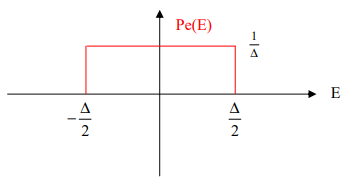
Fig: PDF of Quantization Error
Quantization error is uniformly distributed and integrated to 1.
σ_QNoise^2 = E(e2) = ∫_(-∆/2)^(∆/2)▒〖(1/∆) e^2 〗de
= (1/∆) . e^3/3 |_(-∆/2)^(∆/2)
= (1/∆) . [((〖∆/2)〗^3)/3 -((-〖∆/2)〗^3)/3] = ∆2/12
Noise in PCM Systems
Signal to Quantization Noise ratio in PCM:
The signal-to-quantization noise ratio is given as:
S/Nq = (Normalized signal power)/(Normalized noise power)
= (Normalized signal power) / (∆2/12) … (i)
The number of quantization values is equal to:
q = 2v
Where v is the number of bits used to represent each level
On the other hand, the step size is represented as
∆ = (2 . Xmax) / 2v
Substitute this value in equation (i), and we get
S/Nq = (Normalized signal power)/(〖[(2 . X_max)/2^v ]〗^2 . 1/12)
Let the normalized signal power is equal to P then the
signal-to-quantization noise will be given by
S/Nq = (3P * 2^2v)/(X_max^2 )
The above equation shows that the output signal-to-noise ratio of
the quantizer increases exponentially with an increasing number of
bits per sample, v. recognizing that an increase in v requires a
proportionate increase in the channel (transmission) bandwidth BT,
we thus see that the use of a binary code for the representation of
a message signal (as in pulse code modulation) provides a more
efficient method than either frequency modulation (FM) or pulse
position modulation (PPM) for the trade-off of increased channel
bandwidth for improved noise performance. In making this statement,
we presume that the FM and PPM systems are limited by receiver
noise, whereas the binary-coded modulation is limited by
quantization error/noise.
Example
Consider the special case of a full-load sinusoidal modulating
signal of amplitude Am, which utilizes all the representation levels
provided. The average signal power is (assuming a load of 1 ohm)
P = (A_m^2)/2
The total range of the quantizer input is 2Am, because the
modulating signal swings between - Am and Am. We may therefore set
Xmax = Am.
Thus the output signal-to-noise ratio of a uniform quantizer,
for a full-load test tone, is
(SNR)o = (A_m^2/2)/((1/3).〖 A〗_m^2.2^(-2v) ) = (3/2) . 22v
Expressing the signal-to-noise ratio in decibels, we get
10log10(SNR)0 = 1.8 + 6v
As the normalized quantizer error is ∆2/12. So, the quantization
error or noise should be
σ_Q^2 = ∆2/12 = 1/3 . X_max^2 . 2^(-2v) [as ∆ = (2X_max)/2^v ]
Or, σ_Q^2 = ∆2/12 = 1/3 . A_m^2 . 2^(-2v)
