
Pulse Amplitude Modulation (PAM), Pulse Width Modulation (PWM), Pulse Position Modulation(PPM), Pulse Coded Modulation & their Demodulation
Pulse Width Modulation (PWM)
Theory
Pulse-Width Modulation (PWM), also called Pulse-Duration Modulation (PDM), is a technique to control the average power delivered by a signal. Instead of changing the amplitude, PWM varies the width of pulses in a pulse train, while keeping the pulse amplitude and frequency constant. By adjusting the pulse width, the average voltage or power supplied to a load can be precisely controlled.
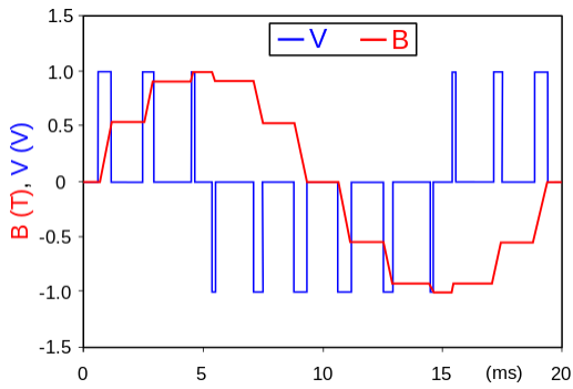
Fig 1: PWM controlling the current in an inductor. The varying-width voltage pulses (blue) create a smoother, sine-like current waveform (red).
The Concept of Duty Cycle
The key concept in PWM is the duty cycle, which is the fraction of time a signal remains 'high' during one period, usually expressed as a percentage.
- 100% duty cycle: Signal is always on.
- 0% duty cycle: Signal is always off.
- 50% duty cycle: Signal is on for half the period and off for the other half, forming a square wave.
A low duty cycle corresponds to low average power, while a high duty cycle corresponds to high average power. This allows precise control over devices such as motors, LEDs, and heaters.
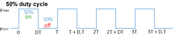
Fig 2: PWM signals with 50% duty cycle. Here, DT represents the pulse width, calculated as DT = D × T, where D is the duty cycle and T is the signal period.
Generation of a PWM Signal
The most common generation method is the intersection method, where a modulating signal is compared to a high-frequency carrier waveform (sawtooth or triangle) using a comparator.
- A high-frequency sawtooth or triangle wave is generated by an oscillator and applied to one input of the comparator.
- The modulating signal (information signal) is applied to the other input of the comparator.
- The comparator outputs a high signal whenever the modulating signal voltage exceeds the carrier voltage; otherwise, it outputs low.
The resulting pulse train has widths proportional to the amplitude of the modulating signal.
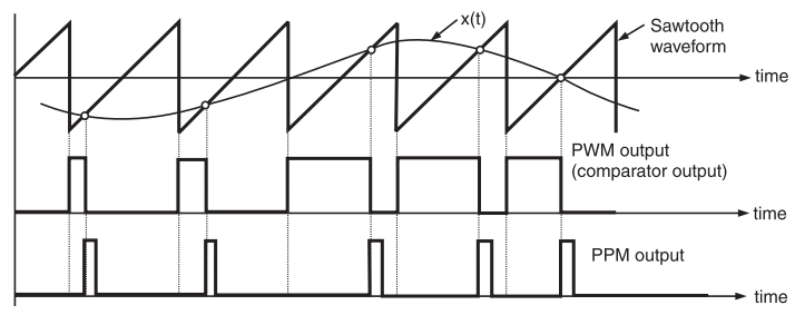
Fig 3: PWM signal generated by comparing a modulating signal with a sawtooth wave.
Demodulation of a PWM Signal
To recover the original modulating signal, the PWM signal must be demodulated. This is typically done by passing the PWM signal through a low-pass filter. The filter averages out the high-frequency pulses, and its output voltage is proportional to the duty cycle of the PWM signal. Since the duty cycle was varied according to the original message signal, the output of the low-pass filter is a reconstruction of that original signal.
Effects of Noise and Distortion
Noise Immunity
PWM has good noise immunity because information is encoded in pulse width, not amplitude. Amplitude noise must be significant to cause misinterpretation of the high or low state, making PWM robust in noisy environments.
Distortion
Distortion mainly occurs due to limited channel bandwidth. Rectangular pulses may have smoothed rising/falling edges, slightly changing pulse widths and introducing errors in the reconstructed signal. Longer transmission paths amplify this effect.
Applications of PWM
PWM is widely used due to its efficiency and noise immunity:
- Power Delivery: Controlling DC motors, heaters, and dimming LEDs.
- Motor Control: Precise speed and torque control in robotics, EVs, and industrial machines.
- Telecommunications: Transmitting analog information over noisy digital channels.
- Audio Amplification: Class-D amplifiers use PWM for high efficiency.
- Voltage Regulation: Switch-mode power supplies regulate DC voltages efficiently using PWM.