
Pulse Amplitude Modulation (PAM), Pulse Width Modulation (PWM), Pulse Position Modulation(PPM), Pulse Coded Modulation & their Demodulation
Pulse Code Modulation (PCM)
Pulse Code Modulation (PCM) is a digital representation of an analog signal. It is the standard method used for converting analog audio, video, and other signals into a digital format for transmission, processing, or storage. In PCM, the amplitude of an analog signal is sampled at regular intervals, and each sample is then approximated to the nearest value within a finite set of discrete levels (a process called quantization). Finally, each discrete level is assigned a unique binary code.
Block Diagram
The PCM process can be broken down into two main parts: the transmitter (which performs analog-to-digital conversion) and the receiver (which performs digital-to-analog conversion).
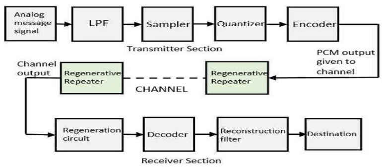
Fig: Block Diagram of a PCM System
Transmitter (Analog-to-Digital Conversion)
- Low-Pass Filtering: Before sampling, the analog signal is passed through a low-pass filter to remove high-frequency components that could cause aliasing.
- Sampling: The filtered signal is sampled at a uniform rate, \(f_s\), which must be at least twice the highest frequency of the signal (the Nyquist theorem). This converts the continuous-time signal into a discrete-time signal.
- Quantization: The amplitude of each sample is rounded to the nearest of a finite number of discrete levels. This is the key step that introduces an approximation error known as quantization noise.
- Encoding: Each quantized level is represented by a unique binary codeword of \(n\) bits. For \(L\) quantization levels, we need \(n = \log_2(L)\) bits.
Receiver (Digital-to-Analog Conversion)
- Regeneration: During transmission, the signal can be corrupted by noise. Regenerative repeaters are used to detect the incoming signal and re-transmit a clean new pulse, preventing noise from accumulating.
- Decoding: The receiver converts the incoming binary codewords back into their corresponding quantized amplitude levels. This creates a staircase-like signal.
- Reconstruction Filtering: The staircase signal is passed through a low-pass filter (the reconstruction filter) to smooth it out and recover an approximation of the original analog signal.
The Quantization Process
Quantization is the process of mapping continuous-amplitude samples to a finite set of discrete amplitude levels. This approximation is necessary for digital representation but is also the main source of error in a PCM system.
Quantization Error (Noise)
The difference between the actual amplitude of a sample and its assigned quantized level is called quantization error. This error is random in nature and manifests as noise in the reconstructed signal. The power of this quantization noise is a critical factor in determining the quality of the PCM system. For a uniform quantizer, the error \(e_q\) for any sample is in the range \(-\Delta/2 \le e_q \le \Delta/2\), where \(\Delta\) is the step size.
The step size \(\Delta\) is given by:
$$ \Delta = \frac{x_{\text{max}} - x_{\text{min}}}{L} = \frac{x_{\text{max}} - x_{\text{min}}}{2^n} $$where \(L\) is the number of quantization levels and \(n\) is the number of bits per sample.
Types of Uniform Quantizers
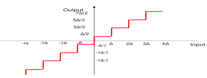
Uniform quantizers have evenly spaced levels. There are two main types:
-
Mid-Tread Quantizer: Has a quantization level at zero. The origin lies in the middle of a "tread" of the staircase transfer function.
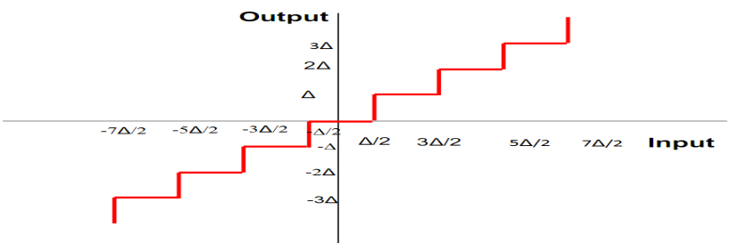
-
Mid-Rise Quantizer: Does not have a level at zero; the origin is in the middle of a "riser".
Noise in PCM Systems
Signal-to-Quantization Noise Ratio (SQNR)
The quality of a PCM system is often measured by the Signal-to-Quantization Noise Ratio (SQNR), which compares the power of the original signal to the power of the quantization noise.
The average power of the quantization noise, assuming the error is uniformly distributed, can be calculated as:
$$ \sigma_e^2 = \frac{\Delta^2}{12} $$The SQNR is then:
$$ \text{SQNR} = \frac{P_s}{\sigma_e^2} = \frac{P_s}{\Delta^2 / 12} $$where \(P_s\) is the average signal power.
By substituting the formula for \(\Delta\), we find that the SQNR is proportional to \(2^{2n}\). When expressed in decibels (dB), this gives a very important rule of thumb:
$$ (\text{SQNR})_{\text{dB}} \approx 1.76 + 6.02n $$This means that for every additional bit used in the encoder, the SQNR improves by approximately 6 dB. This demonstrates the trade-off between signal quality and the number of bits required.
Bit Rate and Bandwidth Requirements
The final output of the PCM encoder is a stream of bits. The rate at which these bits are produced is called the bit rate.
The bit rate (\(R_b\)) is calculated as:
$$ R_b = n \times f_s $$where \(n\) is the number of bits per sample, and \(f_s\) is the sampling rate.
The bandwidth required to transmit this digital signal is generally greater than the bandwidth of the original analog signal. This is the price paid for the robustness, noise immunity, and other advantages of digital transmission.
Demodulation
-
Signal Regeneration
In any practical communication system, the digital signal becomes distorted by noise and weakened (attenuated) as it travels over the channel. Before the signal can be decoded, it must be cleaned up. This is the job of the regenerative circuit.
Its purpose is to receive the weak, distorted pulses and recreate them as a clean, perfectly formed digital signal. It does this by sampling the incoming signal and deciding if each bit is a '1' or a '0', then generating a brand new pulse. This step is crucial for preventing the accumulation of noise in long-distance communication.
-
Decoding
Once a clean digital stream is available, the Decoder takes over. Its function is to convert the digital codewords back into amplitude levels. The process is as follows:
- The decoder groups the incoming bits into the original codeword size (e.g., 8 bits, 16 bits).
- For each binary codeword, the decoder outputs a single voltage pulse with a specific, constant amplitude that corresponds to the quantized level represented by that code.
The output of the decoder is a staircase signal. This signal is a discrete-time, discrete-amplitude approximation of the original analog signal.
-
Reconstruction
The final stage is to convert the blocky staircase signal into a smooth, continuous waveform. This is accomplished by the Reconstruction Filter, which is a high-quality low-pass filter.
The sharp edges of the staircase signal contain many high-frequency components that were not present in the original signal. The low-pass filter removes these unwanted high frequencies, effectively smoothing out the steps and recovering the original analog message signal.
Applications of PCM
Because it is the most fundamental and direct method of digital representation for analog signals, PCM is the bedrock of modern digital communication and media. Its applications are vast and ubiquitous.
- Digital Telephony: This is the original and most well-known application. The international standard for digitizing a voice call for the Public Switched Telephone Network (PSTN) uses PCM. Modern Voice over IP (VoIP) systems also use PCM as the underlying encoding before compression.
-
Digital Audio: PCM is the standard for high-fidelity digital audio.
- Audio CDs: The audio on a standard Compact Disc is stored as uncompressed 16-bit PCM data sampled at 44.1 kHz.
- Computer Audio Files: The common
.WAV(Windows) and.AIFF(Mac) file formats are essentially containers for raw, uncompressed PCM data. - Professional Audio: Recording studios and audio production workflows rely on high-resolution PCM (e.g., 24-bit/96 kHz) for the highest quality.
- Digital Video: The audio track in many digital video formats is stored using PCM. For example, the high-quality audio tracks on Blu-ray discs and in professional video files are often uncompressed multi-channel PCM.
- Satellite and Deep Space Communication: In environments where signals are extremely weak and noise is a major issue, the robustness of PCM makes it an ideal choice for transmitting scientific data and telemetry reliably.
- Integrated Services Digital Network (ISDN): PCM is used to transmit both voice and data over digital telephone lines in ISDN systems.