
Principal Stresses Experiment
Physical Concept
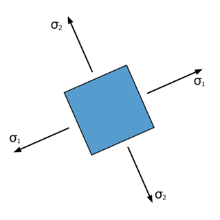
Structural and machine components are often subjected to forces acting in multiple directions simultaneously. As a result, both normal and shear stresses may exist at a point within the material. Such a condition is known as a plane stress state when the stresses act in a two-dimensional plane.
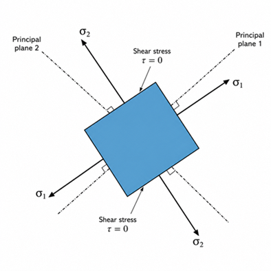
Although stresses may initially act on arbitrary planes, there always exists a particular orientation where the shear stress becomes zero. The normal stresses acting on these mutually perpendicular planes are called the principal stresses. These are the maximum and minimum normal stresses experienced by the material and are fundamental in predicting yielding and failure.
By rotating the stress element to the principal planes, the shear stress disappears and only the principal stresses remain.
Everyday Intuition
Combined loading occurs in many engineering components, such as:
- Rotating shafts subjected to bending and torsion
- Pressure vessels under internal pressure
- Bridge members carrying moving loads
- Crane hooks
- Machine frames
- Aircraft structures
Although these components experience complex combinations of stresses, engineers simplify the analysis by determining the principal stresses acting at critical locations.
Experimental Relevance
This experiment demonstrates how a general plane stress state can be transformed into its corresponding principal stress state.
The experiment enables the learner to determine:
- Maximum principal stress
- Minimum principal stress
- Orientation of the principal planes
- Maximum in-plane shear stress
- Equivalent stresses based on the Tresca and Von Mises yield criteria
These quantities help engineers evaluate whether a component is likely to yield under the applied loading.
Mathematical Formulation
For a plane stress condition,
- Normal stress in the x-direction:
- Normal stress in the y-direction:
- Shear stress:
The principal stresses are
The orientation of the principal planes is
The maximum in-plane shear stress is
For ductile materials, yielding is commonly evaluated using two failure theories.
Tresca (Maximum Shear Stress Criterion)
According to the Tresca criterion, yielding begins when the maximum shear stress reaches the value corresponding to yielding in a uniaxial tensile test.
For plane stress,
This criterion generally provides a conservative estimate of yielding.
Von Mises (Distortion Energy Criterion)
The Von Mises equivalent stress is
Yielding is predicted when
where is the material's yield strength obtained from a tensile test.
The Von Mises criterion is widely used because it provides accurate predictions for ductile materials subjected to combined loading.
Apparatus-Specific Application
In this virtual experiment, the user specifies the applied stress components and the orientation of the stress element.
The simulation calculates:
- Principal stresses
- Principal plane orientation
- Maximum shear stress
- Tresca equivalent stress
- Von Mises equivalent stress
The calculated values allow the user to study how changes in the applied stresses affect the stress state and the likelihood of yielding.
Engineering Significance
Principal stress analysis forms the basis of mechanical and structural design because most engineering components operate under combined loading rather than simple tension or compression.
Applications include:
- Rotating shafts
- Pressure vessels
- Bridges
- Aircraft structures
- Automobile chassis
- Machine frames
- Crane hooks
- Heavy industrial equipment
Understanding principal stresses and failure criteria enables engineers to design safer, more reliable, and more efficient components while preventing yielding and structural failure.