
Parity checker / generator 
Procedure
- Design the below Parity generator and Parity checker circuits
- Verify the Parity generator and Parity checker tables explained in theory
Parity generator
Y = A ⊕ B ⊕ C
Circuit diagram
4-bit Parity checker:
(A ⊕ B) ⊕ (C ⊕ P)
Circuit diagram
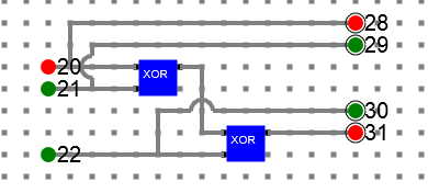
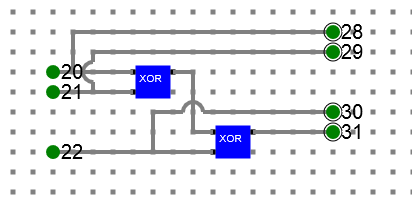
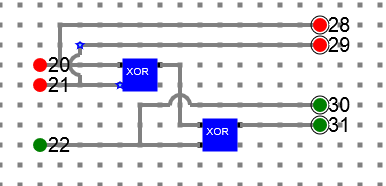
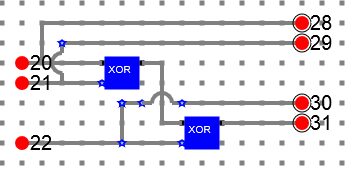
- Below is the even parity generator circuit diagram for a 3 bit data. Data bits are represented by label 20, 21, 22 and the parity bit is represented with label 31. Final data including parity will be 28, 29, 30, 31. Even parity will make sure there are even number of 1’s at the output including parity.
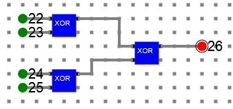
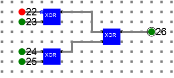
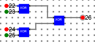
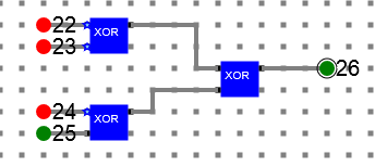
- Below is the even parity checker circuit diagram for a 4 bit message. The bit represented by label 26 shows if there is any error (Green) or not (Red). It is clearly visible, if there is even number of 1’s in the data, then parity checked is low means no error. Otherwise it is high means there is some error in the data.
Refer the simulator manual on how to design the circuit
- Manual --> Click Here