
Measurement of Self Inductance by Owen Bridge 
Procedure
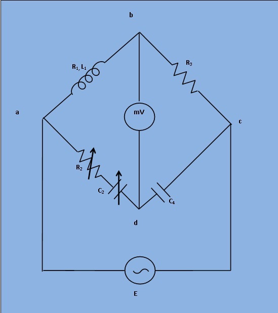
Fig. 1. Circuit digram of experimental set-up for Owen's Bridge
1. Apply Supply voltage from the signal generator with arbitrary frequency. ( V =3v). Also set the unknown Inductance value from 'Set Inductor value' tab.
2. Then switch on the supply to get millivoltmeter deflection.
3. Choose the values of R2, R3, C2 and C4 from the resistance and capacitance box. Varry the values of R2 and C2 by fixing the values of R3 and C4 to some particular values to achieve Null.
4. Observe the millivoltmeter pointer to achieve "NULL".
5. If "NULL" is achieved, switch to 'Measure Inductor value' tab and click on 'Simulate'. Observe the calculated values of unknown inductance (L1) and unknown internal resistance (R1) of the inductor.
6. Also observe the Dissipation factor of the unknwown inductor which is defined as
$$ \frac{\omega L} {R} \ Where, \ \omega=2\pi f $$