
Familiarisation with Oscilloscope and Function Generator
Procedure
- Connect the components as mentioned below: L1-L5, L3-L6, L4-L7, L2-L7.(For eg. click on 1 and then drag to 5 and so on.)
- Click on 'Check Connection' button to check the connections.
- If connected wrong, click on the wrong connection. Else click on 'Delete all connection' button to erase all the connections.
- Connect L1-L5. This will connect the function generator 1 to channel 1 probe of oscilloscope.
- Connect L3-L6. This will connect the function generator 2 to channel 2 probe of oscilloscope.
- Connect L4-L7, L2-L7. This will connect the ground of function generator 1 and function generator 2 with oscilloscope.
- Click on 'ON' button to start the experiment.
- Double Click on 'Sine Wave' button to generate input waveform (2 Vp-p, 1kHz) from Function Generator 1.
- Double Click on 'Sine Wave' button to generate input waveform (2 Vp-p, 1kHz) from Function Generator 2.
- Vary the Amplitude, Frequency, volt/div using the controllers.
- Double Click on "Dual" button to observe both the waveform.
- Click on "X-Y" button to observe the specialized two-channel mode of oscilloscope. The XY time mode converts the oscilloscope from a volts-versus-time display to a volts-versus-volts display using two input channels. Channel 1 is the X-axis input, channel 2 is the Y-axis input.
- Channel 1 shows the waveform of Function Generator 1, Channel 2 shows the waveform of Function Generator 2.
- Repeat step 10-12 for 'Square Wave' and 'Triangular Wave'. Double Click on input button to generate input waveform (2 Vp-p, 1kHz) from Function Generator 1 and Function Generator 2.
- Note : Sometimes due to page load or cache, the graph may not come exact at one click. So it is better to double click on the channel-1 function/ channel-2 function/ dual function/ground function to get the respective signals.
- Oscilloscope and function generator is described more elaborately in the Oscilloscope Tutorial section.
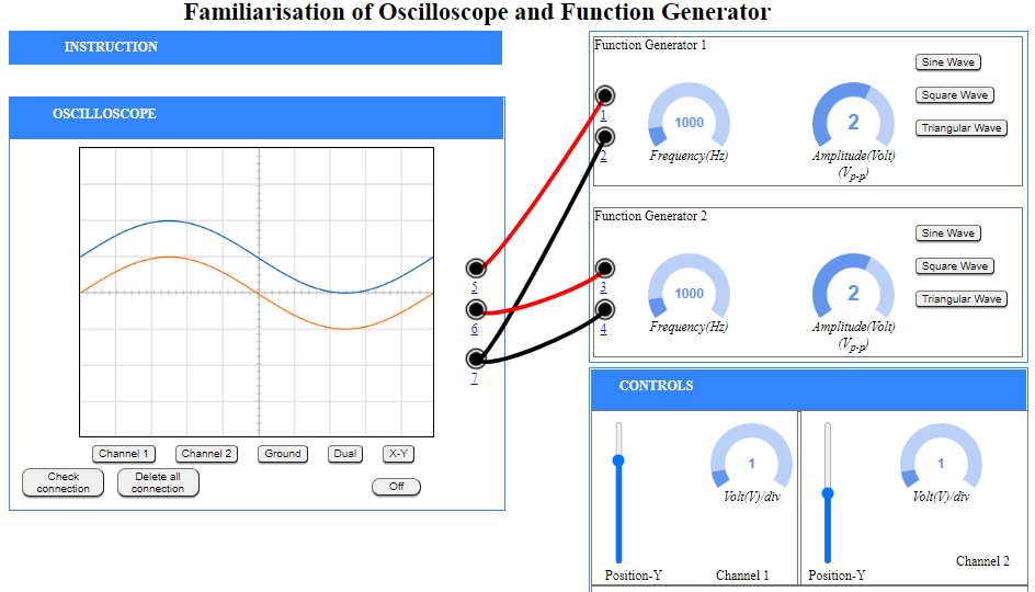
Figure 1
Note
- The input sine wave is 2 Vp-p, 1kHz
- As, volt/div is set to 1 volt/div. Which implies each mazor division is 1 volt where as each minor division is 0.2 volt.
- Click on Sine Wave from function generator 2.
- As, volt/div is set to 1 volt/div. Which implies each mazor division is 1 volt where as each minor division is 0.2 volt.
- Click on "Channel 1" or "Channel 2" button to observe input waveform.
- Double Click on "Dual" button to observe both the waveform
- The ground setting disconnects the input signal from the vertical system, which lets you see where zero volts is located on the screen. With grounded input coupling and auto trigger mode, you see a horizontal line on the screen that represents zero volts. Switching from DC to ground and back again is a handy way of measuring signal voltage levels with respect to ground.
- Click on "X-Y" button to observe the specialized two-channel mode of oscilloscope. (X-Y mode is a specialized two-channel mode of oscilloscopes when the signal of channel 1 is used for the deviation along the horizontal axis (X) and the signal of channel 2 – along the vertical axis (Y).)