Determination of Reynolds Number at various Flow Conditions
Introduction
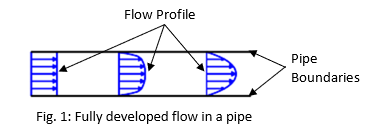
Fluid flow in circular and noncircular pipes is commonly encountered in practice. The hot and cold water that we use in our homes is pumped through pipes. Water in a city is distributed by extensive piping networks. Oil and natural gas are transported hundreds of miles by large pipelines. Fig. 1, the inflow, the velocity profile is often uniform but a thin boundary layer develops on the pipe wall because of friction as the fluid moves along the length of the pipe. Fully developed flow occurs when the viscous effects due to the shear stress between the fluid particles and pipe wall create a fully developed velocity profile. In order for this to occur the fluid must travel through a length of a straight pipe. In addition, the velocity of the fluid for a fully developed flow will be at its fastest at the center line of the pipe. On the other hand, the velocity of the fluid at the walls of the pipe will theoretically be zero. Beyond this distance the velocity profile becomes fully-developed (i.e., doesn’t change any further with downstream distance).
Components of Experimental setup
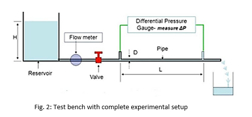
Fig. 2, shows a schematic of test rig or bench for determination of frictional losses in a pipe, who’s each part is explained as follow:
Flow Meter
The test bench consists of flow meter for the experiments. The meter shows the amount of water flowing through the pipe.
Control Valve
A Control valve is provided through which the flow rate of the water flowing through the pipes is controlled. Through this valve, one can make flow laminar or turbulent.
Pipe System
Piping System of size 0.0235 m diameter with length of L = 1.817 m.
Measuring Tank
The measuring tank is equipped with a gauge glass and scale arrangement for quick and easy measurement of the water height filled in the tank.
Differential Manometer
Two pressure tappings are provided one on either end of the pipe length L = 1m. The difference in the reading of the pressure tappings will provide the pressure drop across the length of the pipe.
Reservoir
Sump is provided to store sufficient water for independent circulation through the unit for experimentation and arranged within the floor space of the main unit.
Theory
The flow of water, oil, air and gas in pipes is of great importance to engineers. In particular, the design of distribution systems depends on the relationship between discharge, 𝑄, diameter, 𝐷, and available head, ℎ. When a fluid flows through a pipe, there is a drop-in pressure in the fluid, since energy is required to overcome the viscous effects or frictional forces exerted by the inner surface of walls of the pipe on the moving fluid. The losses due to friction are known to as major losses (hf) while losses through fittings, etc., are called minor losses.
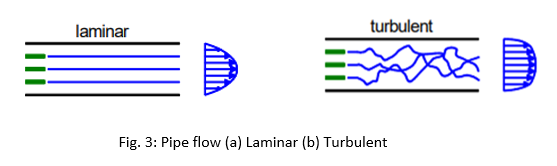
Flow in a pipe is divided mainly into two flow regimes i.e. Laminar and Turbulent flow. The regimes are estimated on the Based on of a dimensionless parameter called the Reynolds number. Reynolds number was named after Osborne Reynolds who demonstrated the occurrence of two regimes of flow in a pipe in the year 1883. Reynolds number is defined as :
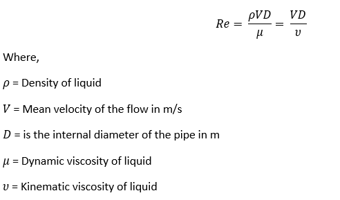
When Re is large, the inertial forces are dominant relative to the viscous forces. Henceforth the viscous forces cannot prevent the random and rapid fluctuations of the fluid i.e. flow becomes Turbulent. At lower Re, the viscous forces are dominant enough to suppress these fluctuations and to keep the fluid “in line”, hence flow remains Laminar.
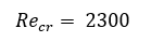
The Re at which the flow becomes turbulent is called the critical Reynolds number, Recr. The value of the critical Reynolds number is different for different geometries and flow conditions. For internal flow in a circular pipe, a value of approximately 2300 is often used as the approximate critical Reynolds number for the start of the transition to turbulence, while flows with a Reynolds number of 4000 or higher are considered fully turbulent.
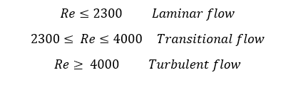
Theoretically it would be nice to have exact values of Reynolds number to define flow regimes for laminar, transitional and turbulent flows but it’s not the case in reality. It is observed that the transition of flow from laminar to turbulent flow depends on many factors i.e. the degree of disturbance of the flow by surface roughness pipe vibrations and fluctuations in the flow. The flow regimes in a circular pipe are taken as:
Furthermore, for a circular pipe with a fully developed flow, the head loss due to friction may be calculated from the formula known as Darcy-Weisbach pipe friction equation : f is known as the Darcy-Weisbach pipe friction factor
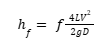
Where,
f = is known as the Darcy-Weisbach pipe
L = Length of the pipe between two tappings in m
V = mean velocity of the flow in m/s
D = is the internal diameter of the pipe in m
g = is the acceleration due to gravity in m/s2
Based on the nature of the flow, friction factor (f) can be estimated using the following correlations :
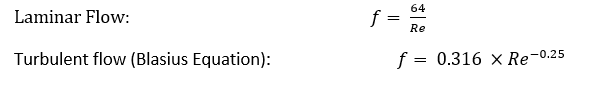
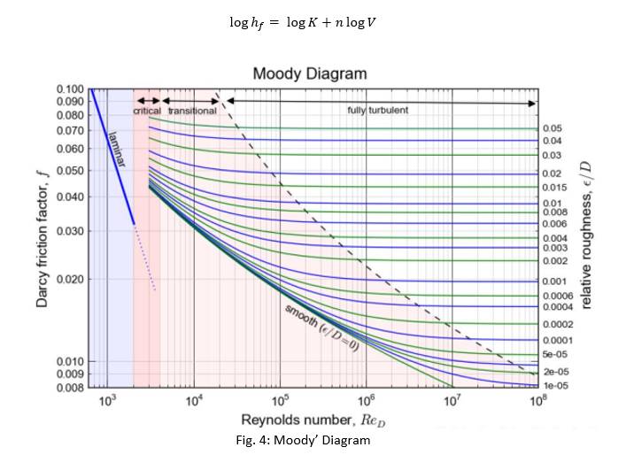
Blasius Equation is valid only for smooth pipe and 3000 < Re < 105. The value of f for turbulent flow can be obtained from the Moody Chart. Moreover, for turbulent flow, the relationship between hf and V is :

Where K is a loss coefficient and n ranges from 1.7 to 2.0 (depending on the value of Re and ks/D). This equation can be rewritten as :