
Multiplexer
2X1 Multiplexer
Circuit Diagram
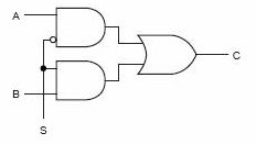
Figure 1: 2X1 Multiplexer circuit diagram showing basic logic implementation with AND, OR, and NOT gates. Reference: Theory section
Components Required
- 2 AND gates
- 1 OR gate
- 1 NOT gate
Note: Input and Output components (A, B, Select, Output) are pre-placed in the simulation workspace.
Circuit Connections
- From the toolbar, drag a NOT gate and connect its input point to the Select input bit.
- Drag the first AND gate from the toolbar and connect its input points to the input bit A and the output point of the NOT gate.
- Drag the second AND gate from the toolbar and connect its input points to the input bit B and the Select input bit.
- Drag an OR gate from the toolbar and connect its input points to the output points of the two AND gates.
- Connect the output of the OR gate to the Output bit in the circuit.
- After setting the values of A, B, and Select click "Simulate".
Additional Features
- Wire Deletion: Right-click on any wire connection and select "Delete" to remove it.
- Component Deletion: Right-click on any logic gate and select "Delete" to remove it.
Observations
- When Select is 0 the output is the value of A and when Select is 1 the output is the value of B.
- If the circuit has been made as described above, a "Success" message will be displayed upon clicking "Submit".
4X1 Multiplexer
Circuit Diagram

Figure 2: 4X1 Multiplexer circuit diagram showing hierarchical construction using three 2X1 multiplexers with select line control. Reference: Theory section
Components Required
- 3 2X1 Multiplexers
Note: Input and Output components (I0, I1, I2, I3, S0, S1, FinalOutput) are pre-placed in the simulation workspace.
Circuit Connections
- From the toolbar, drag the first 2X1 Multiplexer and connect its input points I0 and I1 to the input bits I0 and I1 respectively.
- Connect its Select input point to the input bit S0.
- Drag the second 2X1 Multiplexer from the toolbar and connect its input points I0 and I1 to the input bits I2 and I3 respectively.
- Connect its Select input point to the input bit S0.
- Drag the third 2X1 Multiplexer from the toolbar and connect its input points I0 and I1 to the output points of first and second Multiplexer respectively.
- Connect its Select input point to the input bit S1 and its output point to the FinalOutput bit of the circuit.
- After setting the values of I0, I1, I2, I3, S0, and S1, click "Simulate".
Additional Features
- Wire Deletion: Right-click on any wire connection and select "Delete" to remove it.
- Component Deletion: Right-click on any multiplexer and select "Delete" to remove it.
Observations
- When S1 is 0 the output of the first 2X1 Multiplexer is the output and when S1 is 1 the output of the second 2X1 Multiplexer is the output.
- The select code S1S0 determines which input (I0, I1, I2, or I3) appears at the output:
- S1S0 = 00: Output = I0
- S1S0 = 01: Output = I1
- S1S0 = 10: Output = I2
- S1S0 = 11: Output = I3
- If the circuit has been made as described above, a "Success" message will be displayed upon clicking "Submit".