
To simulate interfacing of multiple sensors (Ultrasonic sensor, PIR Sensor, DHT sensor, Soil Moisture, MQ135 Sensors) with Arduino.
Objective
The objective of this experiment is to simulate and understand the interfacing of multiple environmental and motion sensors—Ultrasonic Sensor, PIR Sensor, DHT Sensor, Soil Moisture Sensor, and MQ135 Gas Sensor—with an Arduino microcontroller.
This experiment aims to provide in-depth knowledge of multi-sensor data acquisition, environmental parameter monitoring, and sensor-based decision making. It also helps learners understand how different sensors with varied output characteristics (digital, analog, and timing-based) can be integrated into a single embedded system.
Introduction
Sensors form the backbone of modern embedded systems and Internet of Things (IoT) applications. A sensor is a device that detects physical, chemical, or environmental changes and converts them into electrical signals that can be processed by a microcontroller.
In real-world systems, a single sensor is often insufficient to describe the surrounding environment accurately. Therefore, multiple sensors are used together to monitor various parameters such as distance, motion, temperature, humidity, soil condition, and air quality. These multi-sensor systems are widely used in applications like smart agriculture, environmental monitoring, industrial automation, healthcare systems, and smart cities.
In this experiment, Arduino acts as a central processing unit that collects data from multiple sensors, processes the sensor readings, and enables intelligent decision making. This simulation demonstrates how different sensors operate simultaneously and how Arduino handles multiple inputs efficiently.
Arduino Sensor Interfacing Theory
Arduino supports multiple sensor interfacing techniques depending on sensor type and output signal characteristics. Sensors connected to Arduino can be broadly classified into:
- Digital Sensors – Provide discrete output (HIGH or LOW)
- Analog Sensors – Provide continuous voltage output
- Timing-Based Sensors – Depend on pulse duration or communication timing
Arduino contains an internal Analog-to-Digital Converter (ADC) that converts analog voltages in the range of 0–5V into digital values between 0 and 1023. This conversion allows Arduino to process real-world analog signals digitally.
To handle sensor data efficiently, Arduino provides built-in functions and supports external libraries that simplify sensor interfacing and ensure accurate readings.
Commonly used Arduino functions include:
digitalRead()– Reads binary output from digital sensorsanalogRead()– Reads analog voltage levels from sensorspulseIn()– Measures pulse duration for timing-based sensors- Sensor-specific libraries – Used for calibration and protocol handling
Components
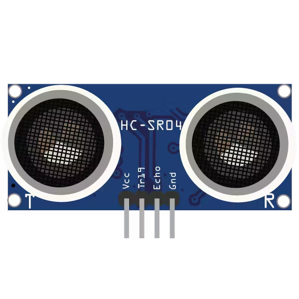
1. Ultrasonic Sensor
Working Principle
An ultrasonic sensor measures distance using high-frequency sound waves beyond the range of human hearing. The sensor emits an ultrasonic pulse through its Trigger pin. When this pulse strikes an object, it is reflected back and received by the Echo pin.
The time taken by the pulse to travel to the object and return is measured. Distance is calculated using the time of flight principle:
Distance = (Speed of Sound × Time) / 2
This method provides accurate distance measurement without physical contact.
Interfacing with Arduino
- Trigger pin connected to a digital output pin
- Echo pin connected to a digital input pin
pulseIn()function used to measure echo time
Applications
- Obstacle detection in robotics
- Distance measurement systems
- Smart parking and vehicle detection
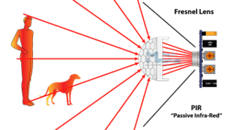
2. PIR Sensor
Working Principle
A PIR (Passive Infrared) sensor detects motion by sensing changes in infrared radiation emitted by warm objects such as humans or animals. The sensor contains pyroelectric elements that respond to variations in infrared energy.
When motion is detected within the sensing range, the PIR sensor outputs a HIGH signal. In the absence of motion, the output remains LOW. Sensitivity and delay time can be adjusted using onboard potentiometers.
Interfacing with Arduino
- Output pin connected to a digital input pin
- No continuous power signal required from Arduino
Applications
- Motion-based security systems
- Automatic lighting control
- Occupancy detection systems
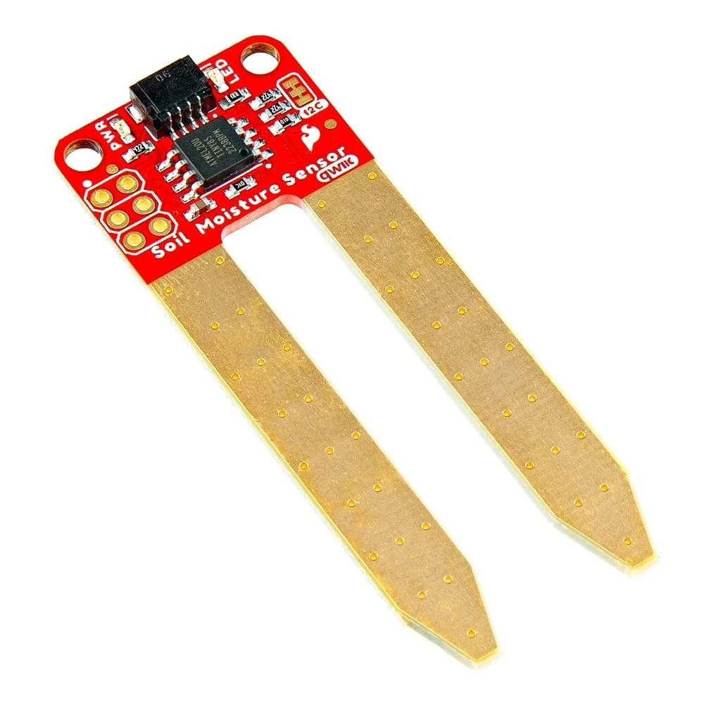
3. Soil Moisture Sensor
Working Principle
A soil moisture sensor determines the water content in soil by measuring its electrical conductivity. Wet soil conducts electricity more efficiently than dry soil, resulting in different resistance values.
These resistance changes are converted into voltage variations, which are read by Arduino as analog values. This enables continuous monitoring of soil moisture levels.
Interfacing with Arduino
- Analog output connected to an analog input pin
- Moisture level interpreted using ADC values
Applications
- Automated irrigation systems
- Precision farming
- Crop health monitoring
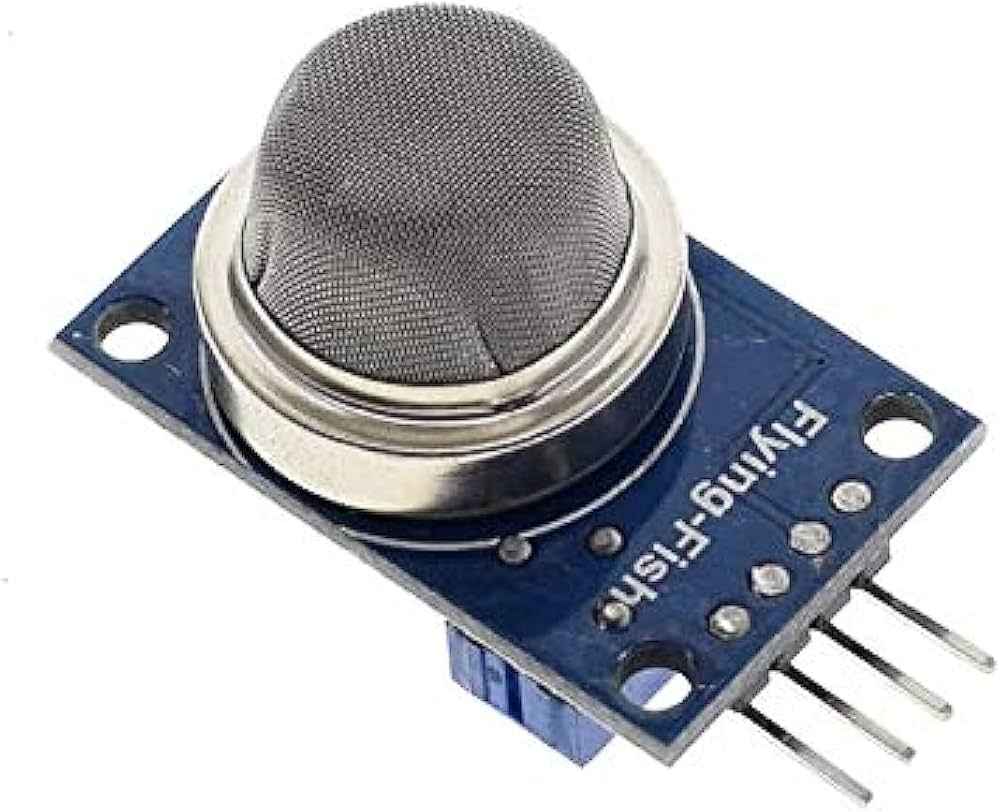
4. MQ135 Gas Sensor
Working Principle
The MQ135 gas sensor is designed to detect air quality and harmful gases such as ammonia, carbon dioxide, benzene, and smoke. The sensing element changes its resistance in the presence of gases, resulting in varying output voltage.
The sensor requires a preheating period to stabilize before accurate measurements can be obtained.
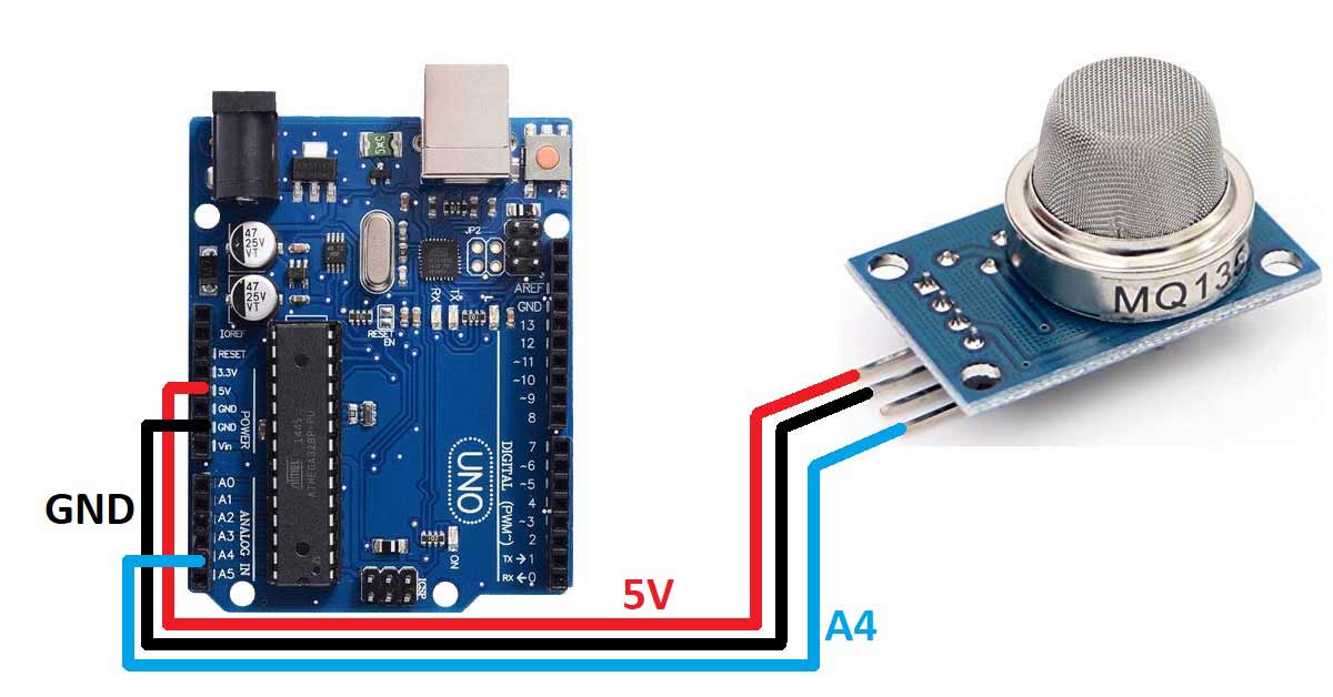
Interfacing with Arduino
- Analog output connected to an analog input pin
- Requires calibration for accurate gas concentration measurement
Applications
- Air quality monitoring
- Pollution detection systems
- Industrial safety applications
Conclusion
This experiment provides a comprehensive understanding of interfacing multiple sensors with Arduino for real-time environmental monitoring. The knowledge gained from this experiment forms a strong foundation for designing advanced embedded systems and IoT solutions such as smart agriculture platforms, environmental monitoring systems, and intelligent automation.
References
- Arduino Official Documentation – https://www.arduino.cc
- HC-SR04 Ultrasonic Sensor Datasheet
- PIR Motion Sensor Datasheet
- Adafruit DHT Sensor Guide
- MQ135 Gas Sensor Datasheet
- Embedded Systems Design – Raj Kamal