
To simulate interfacing of multiple motors (DC Motor, Servo Motor and Stepper Motor) with Arduino
Introduction
Motors are electromechanical devices that convert electrical energy into mechanical motion. They play a crucial role in embedded systems, robotics, automation, and industrial control applications where movement and actuation are required.
In this experiment, different types of motors such as DC motor, servo motor, and stepper motor are interfaced with an Arduino microcontroller. The experiment introduces learners to essential motor control concepts including speed control, direction control, position control, and step-wise rotation. Since Arduino cannot directly drive motors due to current limitations, external motor drivers are used for safe and efficient operation.
Arduino and Motor Control Basics
Arduino controls motors using various control techniques depending on the motor type:
- Digital control signals – Used for direction and ON/OFF control
- PWM (Pulse Width Modulation) – Used for speed and position control
- External motor drivers – Used to handle high current and voltage requirements
Key Limitations of Arduino:
- Arduino I/O pins provide very low current
- Motors require higher current and voltage
- Direct connection may damage the Arduino
2. Electrical and Control Considerations
2.1 Microcontroller Limitations
Arduino I/O pins operate at logic-level voltages (5V or 3.3V) and can supply limited current, generally in the range of 20–40 mA. In contrast, motors require significantly higher current and behave as inductive loads. Sudden switching of inductive loads generates back electromotive force (back EMF), which can damage semiconductor components if not properly managed.
Therefore, external motor driver circuits are necessary to:
Amplify current,
Provide bidirectional control,
Protect the microcontroller from voltage transients.
2.2 Pulse Width Modulation (PWM)
Motor speed control is commonly achieved using pulse-width modulation. In PWM, the supply voltage is rapidly switched ON and OFF at high frequency. The average voltage applied to the motor is proportional to the duty cycle. By varying the duty cycle, precise speed regulation can be achieved without significant power loss. Digital signals are used alongside PWM to define direction and switching states.
Components
1. DC Motor
1.1 Operating Principle
A DC motor consists of a stator that produces a magnetic field and a rotor (armature) carrying current. When voltage is applied, torque is generated due to electromagnetic interaction:
T∝ΦIa
where Φ is magnetic flux and Ia is armature current. As the motor rotates, it produces back EMF proportional to speed, which regulates current and stabilizes operation.
3.2 Speed and Direction Control
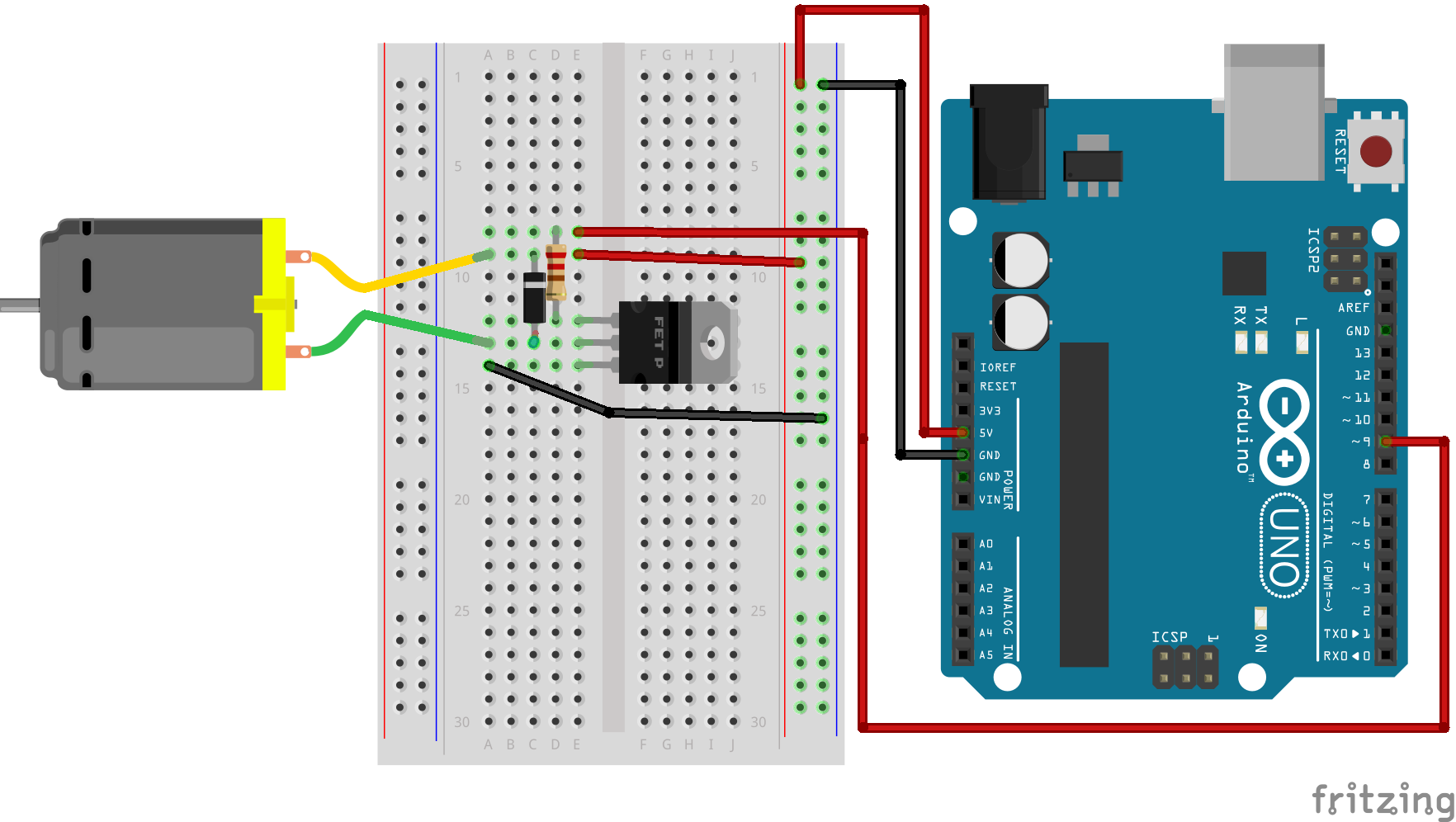
The speed of a DC motor is approximately proportional to the applied voltage and can be controlled using PWM. Direction control is achieved by reversing the polarity of the supply voltage. In embedded systems, this is implemented using an H-Bridge driver such as L298N, which allows electronic reversal of current flow.
DC motors are suitable for applications requiring continuous rotation, such as robotic wheels, pumps, and ventilation systems.
Applications:
- Fans
- Wheels in robotic vehicles
- Water pumps
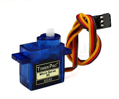
2. Servo Motor
2.1 Internal Structure and Feedback Mechanism
A servo motor integrates a DC motor, gear reduction system, position sensor (typically a potentiometer), and an internal control circuit. Unlike open-loop systems, servo motors operate on closed-loop control principles.
The control signal, typically a PWM waveform at approximately 50 Hz, determines the desired angular position. The internal controller continuously compares the commanded position with the actual shaft position and minimizes the error through corrective motion.
2.2 Position Control Characteristics
Pulse widths between approximately 1 ms and 2 ms correspond to angular positions between 0° and 180°. Because of the internal feedback mechanism, servo motors provide accurate and stable angular positioning, making them ideal for robotic arms, steering mechanisms, and camera alignment systems.
Applications:
- Robotic arms
- Camera positioning systems
- Steering mechanisms
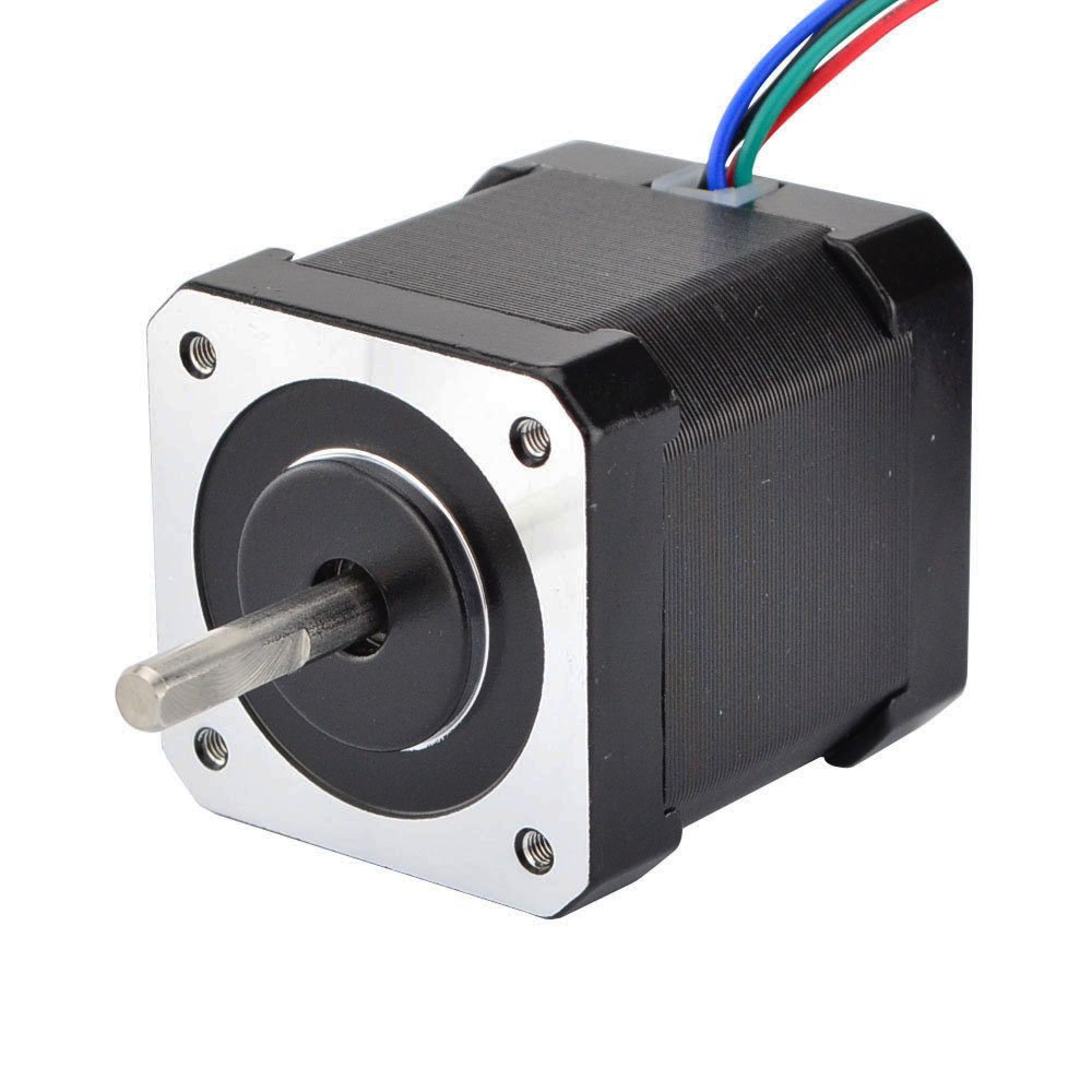
3. Stepper Motor
3.1 Discrete Step Operation
A stepper motor rotates in discrete angular increments. Each input pulse causes the shaft to move by a fixed angle, commonly 1.8°, resulting in 200 steps per revolution. Motion is achieved by sequentially energizing internal windings to create a rotating magnetic field.
5.2 Control and Precision
Stepper motors operate effectively in open-loop configuration, where position is determined by counting input pulses. Speed depends on pulse frequency, and direction depends on the sequence of phase excitation. Dedicated driver modules such as ULN2003 or A4988 are used to handle current amplification and coil switching.
Applications:
- CNC machines
- 3D printers
- Precision positioning systems
Circuit Connections
DC Motor Connection
- Motor terminals connected to H-Bridge driver
- Driver input pins connected to Arduino digital pins
- PWM pin used for speed control
Servo Motor Connection
- Signal pin connected to Arduino digital pin
- Power and ground connected to external supply if required
Stepper Motor Connection
- Motor connected to stepper driver
- Driver control pins connected to Arduino digital pins
- Step sequence controlled via code
Engineering Significance
The interfacing of DC, servo, and stepper motors demonstrates three distinct control paradigms: voltage-based continuous rotation, feedback-based angular positioning, and pulse-based discrete motion control. Understanding these approaches enables proper actuator selection in embedded and IoT systems.
Through this experiment, learners gain practical and theoretical insight into electromagnetic torque generation, driver circuit necessity, PWM-based control, and system-level safety considerations. Such knowledge forms the foundation for advanced robotic and automation system design.
Conclusion
This experiment demonstrates the interfacing and control of multiple types of motors using Arduino. Understanding motor control techniques such as speed control, direction control, and position control is essential for developing robotics, automation, and motion-based embedded systems.