Bulk and Micro Hardness Test of Materials
Brief Description of the Equipment/Machine:
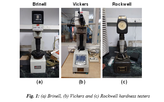
a. Brinell hardness tester: The Brinell hardness tester is shown in Fig. 1a. The Brinell hardness test method consists of indenting the test material with a 10 mm diameter hardened steel or carbide ball subjected to a load of 3000 kg. For softer materials, the load can be reduced to 1500 kg or 500 kg to avoid excessive indentation.
b. Vickers hardness tester: The Vickers indenter is shown in Fig. 1b. A very small diamond indenter having pyramidal geometry is used for indentation. This tester provides automatic measurement of hardness from the measured lengths of diagonals of indentation impression.
c. Rockwell hardness tester: The Rockwell hardness tester is shown in Fig. 1c. The indenter consists of diamond cone indenter.

Theory: In general, hardness (H) is calculated by applied load (P) divided by the surface area (A) of the indentation impression, i.e., H = P/A.
a. Brinell hardness: The diameters (d1 and d2) of the impression left by the indenter in the test material is measured using a microscope, as shown in Fig. 2. Brinell hardness (in BHN) is given by:

where D is the diameter of the ball indenter, P is the applied load in kgf, d is the average diameter of the impression (Fig. 2).
The diameter of the impression (d) is the average of two readings at right angles, i.e., d1 and d2. Brinell hardness number is generally represented as "75 HB 10/500/30", which means that a Brinell Hardness of 75 was obtained using a 10 mm diameter hardened steel with a 500 kilogram-force (kgf) load applied for a period of 30 seconds. While testing extremely hard metals, a tungsten carbide (WC) ball is substituted for the steel ball.

b. Vickers hardness: A very small diamond indenter having pyramidal geometry (angle between opposite faces is 136°) is forced into the surface of the specimen. Applied loads are much smaller than for Rockwell and Brinell, ranging between 1 and 1000 g. The resulting impression is observed under a microscope and diagonals (d1 and d2) are measured, as shown in Fig. 3. Vickers hardness number (in HV) is given by:

where P is the applied load in kgf and d is the average diagonal length (see Fig. 3).

c. Rockwell hardness: The Rockwell hardness test method consists of indenting the test material with a diamond cone or hardened steel ball indenter. The indenter is forced into the test material under a preliminary minor load Fo (Fig. 4a), usually 10 kgf. When equilibrium has reached, an indicating device, which follows the movements of the indenter and so responds to changes in depth of penetration of the indenter, is set to a datum position. While the preliminary minor load is still applied, an additional major load is applied resulting in an increase in the penetration (Fig. 4b). When equilibrium has reached again, the additional major load is removed but the preliminary minor load is still applied. Removal of the additional major load allows a partial recovery, reducing the depth of penetration (Fig. 4c). The permanent increase in the depth of penetration, resulting from the application and removal of the additional major load is used to calculate the Rockwell hardness number (HR). Rockwell indenter automatically provides values of hardness.
The steps involved in the Rockwell hardness test are shown in Fig. 5. Table 1 shows the data pertaining to regular Rockwell indenter.

Rockwell hardness value is given by, HR = E - e


