
Measurement of Self-Inductance by Maxwell's Bridge 
Introduction
In this bridge, an inductance is measured by comparison with a standard variable capacitance. The connection is shown in Figure 1.
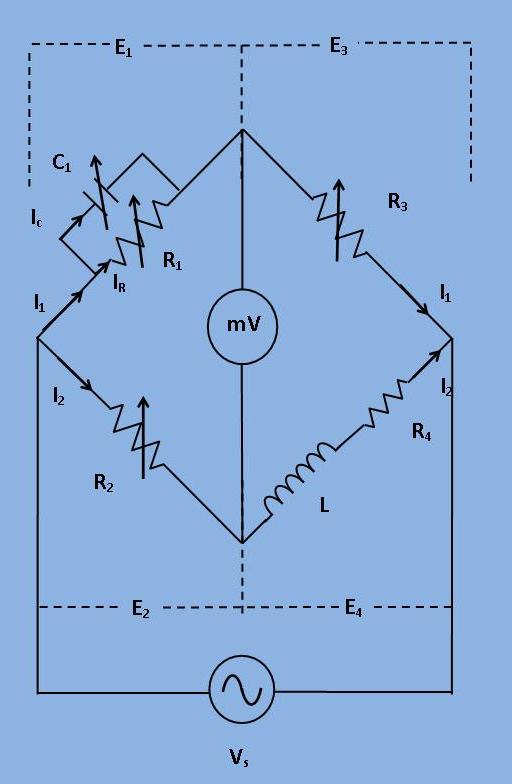
Figure 1: Circuit diagram for Maxwell's Bridge
Here,
L = Unknown Inductance,
R4 = Effective resistance of unknown Inductance coil,
R1, R2, R3 = Known non inductive resistance,
C1 = Standard variable capacitor.
L = Unknown Inductance,
R4 = Effective resistance of unknown Inductance coil,
R1, R2, R3 = Known non inductive resistance,
C1 = Standard variable capacitor.
The balance equation for the branch can be written as:
$$ (R_4 + j\omega L) * (\frac{R_1}{1 + j\omega C_1R_1}) = R_2R_3; $$ $$ R_1 R_4 + j\omega L R_1 = R_2 R_3 + j\omega R_2 R_3 C_1 R_1; $$
Equating the real and imaginary parts,
$$ R_4 = \frac{R_2 R_3}{R_1} ...... (1)$$ $$ L = R_2 R_3 C_1 ...... (2)$$
Two variables R1 and C1 which appear in one of the two balance equations (i.e. equation (1) and (2)) and hence the two equations are independent. The expression for Q factor can be written as:
$$ Q = \frac{\omega L}{R_4} = \omega C_1 R_1 \ Phasor \ Diagram: $$
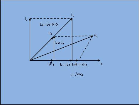
Fig 2: Phasor diagram for the circuit shown in Figure 1