
Measurement of Flatness of a Surface using Autocollimator
Procedure
Steps to perform the simulation
To follow instructions on the simulation page click on the blue Instructions tab there.
Measurement of flatness of a surface using Autocollimator:
- First click on the green power button to switch on the monochromatic light source. The reflector will be at the zero position first (0-110 mm). There will be missalignment between target graticule and setting graticule horizontal lines in the reflected image on the reflector.
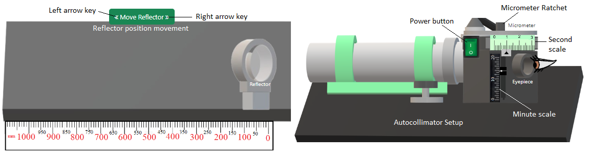
Fig. 1. Measurement of alignment using Autocollimator simulation model
Click on the ratchet of the micrometer until the horizontal lines of setting and target graticule coincides.
Click on 'Calculate' button to observe the measurements. Click on 'Table' at the bottom of the page and click on 'Show Table' button to tabulate the readings.
Switch off the power button. Now move the reflector to next position (110-220 mm) in the left by clicking on the left side arrow key of 'Move Reflector' button once. Follow steps 1-3 to note the second observation.
Follow step 4 again for positions 220-330, 330-440, 440-550, 550-660, 660-770 and 770-880 mm. At the end eight observations will be generated.
Now click on "Cumulative Error (µm) Vs. Position (mm)" or "Error from horizontal straight line (µm) Vs. Position (mm)" under 'Plot' to observe the plots.
Click on 'Clear' button.