
Measurement of Data Rate for Digital Optical Link.
Procedure
- Connect the TechBook Power Supply with mains cord to TechBook Board
- Make the connections as shown in figure 1
- Connect the 1 KHz square wave from Function Generator to emitter input.
- Connect the fiber optic cable between emitter output and detector input.
- Connect the detector output to comparator input.
- Put the mode switch SW1 to Digital to drive the emitter in Digital mode. This ensures that signal applied to the driver input cause the emitter LED to switch quickly between ‘On’ & ‘Off’ states.
- Switch ‘On’ the Power Supply of TechBook and Oscilloscope.
- Examine the input to emitter on an Oscilloscope this 1 KHz square wave is now being used to amplitude modulates emitter LED.
- Examine the output of detector. This should carry a smaller version of original 1 KHz square wave illustrating that the modulated light beam has been reconverted into an electrical signal.
- Monitor inputs of comparator and slowly adjust the comparator bias potentiometer until the DC level on the negative input lies mid-way between the high & low level of the signal on the positive input. This DC level is comparator's threshold level.
- Examine the output of comparator. Note that the original digital modulating signal has been reconstructed at the receiver.
- Change the frequency of square wave input to 10 KHz. Observe the received output on the Oscilloscope.
- Note the frequency at which the output is distorted or has become zero. The bit rate supported by the link is twice the frequency reading corresponding to zero/ distorted output in bits per second.
So, the Formula to calculate the Data rate is given by:
Data rate = 2 * f
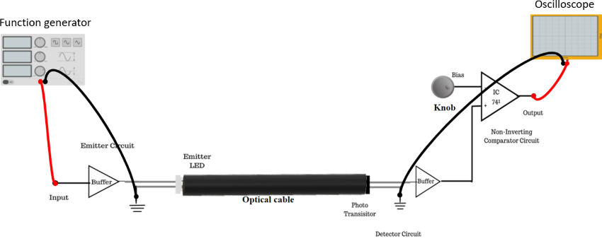
Figure 1: Set up for Measurement of data rate for digital optical link