Lesson 2: Forging Process
📥 Lesson 2 Download- 2.0 Introduction
- 2.1 Applications of Forging
- 2.2 Metals and their forging temperatures
- 2.3 Measurement of forging temperatures
- 2.4 Classification of Forging
- 2.5 Forging Operations
- 2.5.1 Upsetting
- 2.5.2 Cogging (Drawing Out)
- 2.5.3 Edging
- 2.5.4 Fullering
- 2.5.5 Blocking
- 2.5.6 Finishing
- 2.6 Types of forging process on the basis of method of application of force
- 2.6.1 Hand Forging
- 2.6.2 Drop Forging
- 2.6.3 Press Forging
- 2.7 Miscellaneous forging processes
- 2.7.1 Coining
- 2.7.2 Rotary Swaging
- 2.7.3 Orbital Forging
- 2.7.4 Flashless Forging
- 2.7.5 Isothermal Die Forging
- 2.7.6 Roll Forging
- 2.8 Dies used for Forging
- 2.9 Lubricants used in Forging
- 2.10 Defects in Forging
- Example
- Terminal Questions
- Comparison of different forging materials
2.0 Introduction
The importance of metals in modern technology is due, in large part, to the ease with which they may be formed, into useful shapes such as tubes, rods, and sheets.
Useful shapes may be generated in two basic ways:
1. By plastic deformation processes in which the volume and mass of metal are conserved and the metal is displaced from one location to another.
2. By metal removal or machining processes in which material is removed in order to give it the required shape.
Forging is the working of metal into a useful shape by hammering or pressing. Various useful shapes are obtained by compressive forces that are applied on workpiece through various dies and tools. The compressive forces for forging are derived either from the impact of a hammer (hand or power operated) or from the pressure exerted by a large mechanical press. Metals in forging are deformed plastically at room temperature (cold forging) as well as at higher temperature (hot forging). The ability to cold forge the metal depends on the ductility and malleability of the metal whereas the ability to hot forge the metal depends on its 'range of plasticity' at higher temperature. The forged components are called forgings.
Cold forging may generally cause anisotropy, a state in which properties of the metal are different in different directions and this effect of cold forging is taken care of by annealing the cold forged component.
The forgeability of a metal is defined as the capability of the metal to undergo deformation without cracking. A commonly accepted test for forgeability is to upset a solid cylindrical specimen and observe any cracking on the barrelled surface, the greater the deformation prior to cracking, the greater the forgeability of metal.
In forging metal may be:
1. drawn out to increase its length and decrease it cross-section.
2. upset to decrease the length and increase the cross-section.
3. squeezed in closed impression dies to produce the desired shape by compelling the metal flow in to multi-directions.
2.1 Applications of Forging
The following common types of jobs are produced by forging:
(i) Box-end wrenches, always made from forgings, are subjected to very high stresses due to hammering; excellent for providing highest torque to tighten the bolts. Casting can not survive.
(ii) Riveting of shells for boilers, tanks and furnaces.
(iii) Machinery parts and steel furniture.
(iv) Bolts, headed pins, nuts, nails, keys, eye bolts, hooks, bolts, shakles, hinges, aldrops, hangers and racks, hooks, links and other lifting tackles for cranes and hoists.
(v) Arms, weapons and cutting tools.
(vi) Agricultural implements and tools.
(vii) Cams, crank shafts connecting rods, axles and levers, etc. for vehicles, locomotives and aircrafts.
(viii) Helical and laminated springs.
(ix) Landing gear cylinders, beams for aircraft wings, turbine disks, gears, wheels.
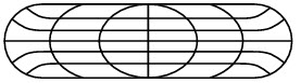
Forging operations produces discrete parts while rolling operations, produce continuous plates, sheets, strip, or various structural cross-sections. Figure 1 shows typical products made from forging operations.
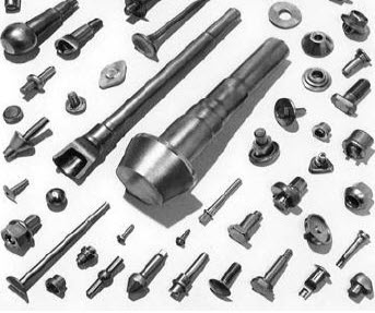
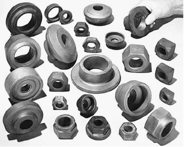
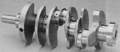
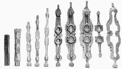
Figure 1: Typical products made by forging, rods, hubs, valve seats, fasteners, crank shaft and connecting rod.
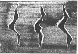
The first question that comes to us is why is it necessary to forge a part to shape when it is simpler and cheaper to cast or machine the metal direct to the form required? It is true that casting or machining process may be cheaper when compared to forging operations for certain products. If the function of a component calls for high strength and resistance to shock or vibration, the properties must be uniform, easily predicted, and measurable within close limits. To achieve this it is usually necessary for steel to be subjected to some form of hot working or forging into more complex shapes. Forging refines the grain structure and improves physical properties of the metal. In forging controlled development of grain flow lines which closely follow the outline of component is obtained (Figures 2, 3, 4 & 5). The continuous grain flow lines increase overall toughness of the forged part and decrease its susceptibility to fatigue and corrosion failures. Internal flaws of the metal are largely eliminated.
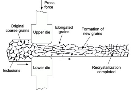
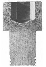
Figure 2: Forging process resulting into the re-crystallization and grain refinement in metals
Figure 3: Cross-section of a forged component showing flow lines.
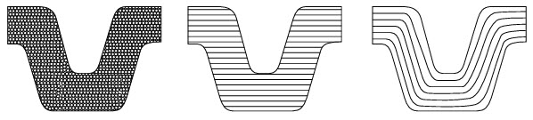
(a) Casting (b) Machined (c) Forged
(a) Casting (b) Machined (c) Forged
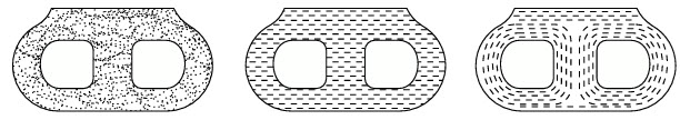
Figure 4: Showing the direction of 'grain flow lines' in a part made by three different processes (a) casting (b) machined from rolled plate (c) Forging
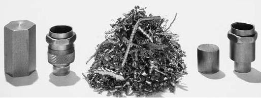
74% waste in machining Chips obtained after machining Cold forged on 6% waste
Figure 5: Comparison of manufacturing of a spark plug body by machining from hexagonal bar stock with manufacture by cold forming. Material is saved, machining time and cost are reduced, and the product is stronger, due to cold work, and tougher
Advantages of forging
(i) Physical properties (such as strength, ductility and toughness) are much better in a forging than in the base metal, which has, crystals randomly oriented. Grains are refined and improved, (Figures 2, 3 & 4).
(ii) Forging produces beneficial grain-flow pattern in the direction of the shape of the forged component, resulting in tough fibrous structure conforming to the outline of the part, (Figures 2, 3 & 4).
(iii) Forging yields parts that have high strength to weight ratio, they can be used reliably for highly stressed and critical applications.
(iv) Forging produces products with higher structural integrity, which are consistent from piece to piece, without any porosity, voids, inclusions and other defects as in case of casting, (Figures 2, 3 & 4).
(v) Reduced testing requirements.
Disadvantages of forging
(i) Hot metal oxidizes rapidly and the scale thus formed gives poor surface finish,
(ii) Close dimensional tolerances on forgings may not be maintained.
(iii) Metal has to be worked within a particular range of temperature: if worked below, it will crack or get distorted and if worked above the required temperature range, it may burn. Hence, too much care is needed while maintaining the optimum temperature for forging.
2.2 Metals and their forging temperatures
The degree to which a metal can be forged depends on its composition and structure. The low and medium carbon steels are readily forged but high carbon and alloy steels are more difficult to forge. The metals and alloys that can be forged include carbon steels, alloy steels, stainless steels, wrought iron, copper base alloys, nickel and nickel-copper alloys, aluminum alloys and magnesium alloys. Cast iron is not forgeable because it has a crystalline structure and when heated and beaten, it breaks into pieces. Every metal has its own forging temperature range at which it goes in plastic state (see Table-1).
| Material to be forged | Temperature range(°C) |
|---|---|
| Mild steel | 815-1250 |
| Medium carbon steel | 760-1250 |
| High carbon steel | 760-1130 |
| Stainless steel | 940-1180 |
| Copper alloys | 550-900 |
| Aluminum and forging alloys | 370-480 |
| Magnesium alloys | 315 |
| Wrought iron | 860-1340 |
2.3 Measurement of Forging Temperatures
Thermocouples are used for measuring temperatures usually from 200 to 1300°C. Then there are optical pyrometers which are used for measuring temperatures in higher range, 700 to 2000°C. Radiation pyrometers are also available for measuring still higher temperatures.
The assessment of temperature of hot metals by seeing its colour is an approximate method of temperature measurement. In case of steels, the following information may be useful (Table-2).
| Colour of the hot metal | Temperature of the hot metal(°C) |
|---|---|
| Red | 600-700 |
| Cherry red | 800-900 |
| Orange | 900-1000 |
| White | 1300-1500 |
2.4 Classification of Forging
Forging can be classified into two categories
1. Open die forging, and
2. Closed die forging
6 (a): Open die forging 6 (b): Closed die forging
2.4.1 Open Die Forging
It is the simplest forging process which is quite flexible but not suitable for large scale production. The operation is carried out between two flat dies or dies of very simple shape, figures 6a & 7. The process of open die forging is carried out in large hydraulic presses or power hammer. Since in open die forging the workpiece is usually larger than the tool, at any point of time, deformation is confined to a small portion of the workpiece. Numerous squeezes or blows are applied to different portions of the workpiece to bring it to the final desired shape. The operator obtains the desired shape of forging gradually and step by step, by manipulating the work material between blows. The resulting size and shape of the forging are dependent on the skill of the operator.
Applications: The process is mostly used for forging large objects of simple shape or when number of parts to be made is small. Open die forging is often used to make preforms (of workpiece) for use in close die forging and large and bulky forgings. Examples of parts made in open die forging include ship propeller shaft, rings, pressure vessels, gun tubes, ring forgings. The process can produce forgings up to 200 tons of weight.
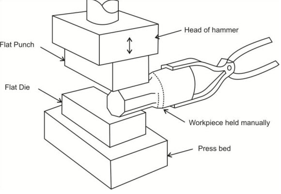
Figure 7: Open die forging (workpiece is held manually and manipulated manually to obtain desired shape).
The open die forging can be explained in the simplest way by the following two open die operations explained in next sections:
(a) Cogging or drawing out
(b) Upsetting
Advantages of open die forging
(i) Simple process
(ii) Dies are inexpensive
(iii) Useful for small quantities
(iv) Wide range of job sizes can be handled
Limitations of open die forging
(i) Limited to simple shapes
(ii) Close dimensional tolerances not possible
(iii) Machining to final shape required if necessary
(iv) Low production rate (v) High degree of skill required
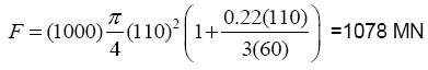
Forging Force
In open die forging operation, the forging force F, to be applied on a solid cylindrical component can be determined from the relation.
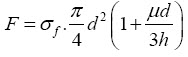
Where
σf is the flow stress of the material, μ is the coefficient of friction, and d and h are the diameter and height of the work piece, respectively.
Example: Using open-die forging operation, a solid cylindrical piece of 304 stainless steel having 100 mm diameter x 72 mm height is reduced in the height to 60 mm at room temperature. Assuming the coefficient of friction as 0.22 and the flow stress for this material at the required true strain as 1000 MPa, calculate the forging force at the end of stroke.
Solution:
Initial diameter = 100 mm
Initial height = 72 mm
Final height = 60 mm
If final diameter is d, (100)2 x 72 = d2 x 60, i.e. d =110 mm
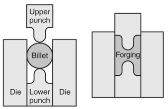
2.4.2 Closed Die Forging (Impression Die Forging)
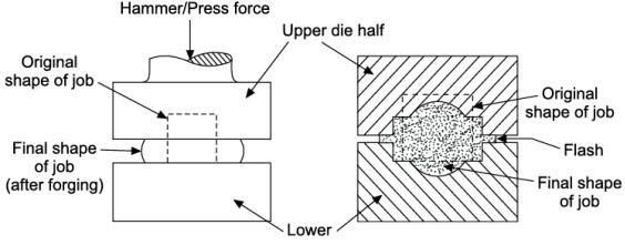
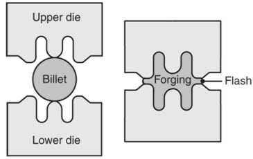
In closed die forging the workpiece is deformed under high pressure between two die halves, which have the impressions of the desired final shape. The heated metal (billet) is positioned in the lower die cavity and on it one or more blows are struck by the upper die. This hammering makes the metal (billet) to flow and fill the die cavity completely. Excess metal is squeezed out around the periphery of the cavity to form flash. On completion of forging, the flash is trimmed off with the help of a trimming die. The work material is given final desired shape in stages as it is deformed in several successive die sets. Thus, a high precision forged with close dimensional tolerances is produced. Closed die forging is shown in Figures 8, 9 &10. The shape of the die cavities cause the metal to flow in desired direction, thereby imparting desired fibre structure to the component. This process is also known as impression die forging.
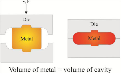
Figure 8: Closed die forging
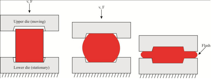
Figure 9: Impression die closed die forging
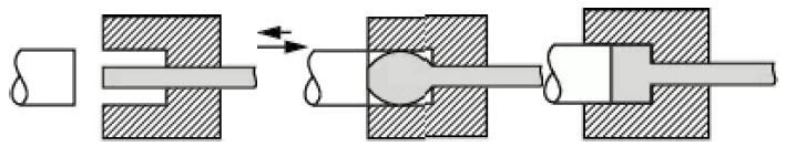
Figure 10: Sample closed die forging (upsetting for producing head of a bolt).
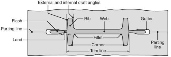
Figure 11: Closed die forging terminology
Advantages of closed die forging
(i) Good utilization of workpiece material
(ii) Better properties than open die forged parts
(iii) Good dimensional accuracy
(iv) Higher production rates
(v) Good reproducibility
Limitations of closed die forging
(i) High cost of dies for small quantities
(ii) Die design more complex
(iii) Machining of forged part is often required
2.5 Forging Operations
Most forgings are obtained in multiple steps with series of dies, where one or more blows of the hammer are used for each step in the sequence. The reason for multi steps is to distribute the metal roughly in accordance with the requirements of the later steps and smooth out the forging force requirement. These processes prepare the workpieces for further forging processes. Few of the forging operations are: Upsetting, Cogging, Edging, Fullering, Blocking and Finishing.
2.5.1 Upsetting
The simplest example of open die forging is the upsetting operation shown in Figure-12. In upsetting, a solid workpiece is placed between two flat dies and reduced in height (but increasing in size in lateral direction) by the application of compressive force. The die surfaces may be flat or having simple cavities to produce relatively simple forgings.
Equipment: Hydraulic, mechanical presses, screw presses; hammers, upsetting machines.
Applications: Finished forgings, including nuts, bolts; flanged shafts, preforms for finished forgings.
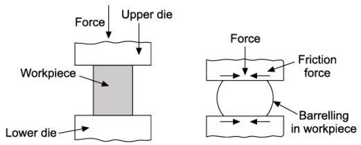
Figure 12: Upsetting operation and barreling effect during upsetting
As the metal flows laterally between the advancing die surfaces, there is less deformation at the die interface because of the friction forces than at the mid-height plane resulting into the barreling of the sides of upset workpiece. Metal flows most easily towards the nearest free surface because that represents the lowest frictional path. Proper lubrication can help reduce the barreling effect. [Figures 12 & 13] (explained in next section).
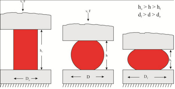
Figure 13: Upsetting operation with friction at die-billet interface
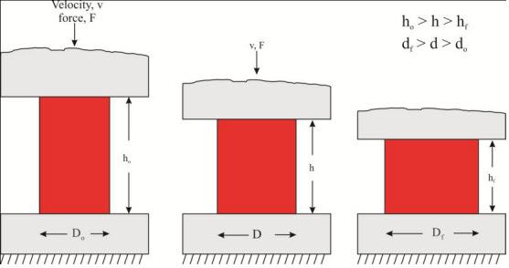
Figure 14: Upsetting operation with out friction at die-billet interface, no barreling


Initial billet (before deformation) Billet after deformation without friction Billet after deformation with friction
Figure 15: Pattern of grain during upsetting without friction and with friction
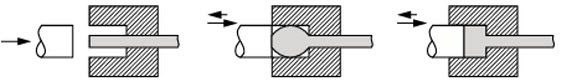
Figure 16: Upsetting used for obtaining head of the bolt
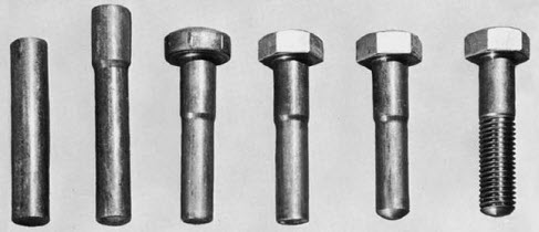
Figure 17: Steps in the forming of head of a bolt by cold heading (upsetting), and thread rolling.
Evolution of bulge in hot upsetting
Successful upsetting mainly depends on two process limitations:
1. Upset strain, ε : that affects the forming limit or forgeability of the workpiece material,
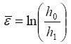
2. Upset Ratio (Ru): that affects the buckling of the workpiece

Where, h0 is the original (before upset) height, h1 is the final height (after upset) and d0 is the original diameter of the billet.
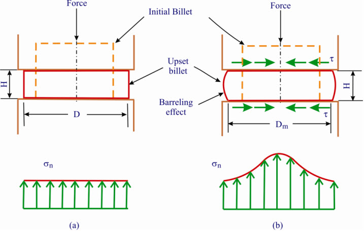
Figure 18: Upsetting of cylindrical workpiece (a) Frictionless. (b) Friction.
To prevent buckling the following rules must be followed in designing parts to be upset forged.
1. The length of the billet to be upset forged should not exceed three times the billet diameter.
2. Length of billet exceeding three times billet diameter may be upset successfully provided the diameter of cavity does not exceed 1 and half times the billet diameter.
3. In an upset requiring stock length exceeding three times billet diameter and where diameter of cavity is not exceeding 1 and half the billet diameter the length of unsupported metal beyond the face of the die must not exceed the diameter of the bar.
2.5.2 Cogging (drawing out)
Cogging is an open die forging operation in which the thickness of a bar (or workpiece) is reduced by successive hammer blows at specific intervals (as shown in Figures-19, 20, 21, 22 & 23). Typical examples of cogging operation are shown in figures 21, 22, & 23. Since the contact area per stroke is small, thickness of workpieces are reduced in stages.
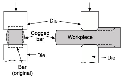
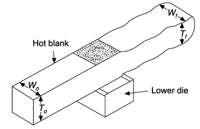
Figure 19: Cogging operation on a rectangular billet conducted with the help of open die forging. The thickness of the bar is being reduced by hammering step by step along the length of bar.
Figure 20: In cogging operations in an open die forging, the portion of billet where contact occurs between the billet and upper die under compression is shown shaded. W0 - Original width of blank, Wf - Width after forging, T0 - Original thickness of billet, Tf - Final thickness after forging.
Initial billet Billet after hammering Completed drawn block
Figure 21: Various stages in drawing down a rectangular billet.
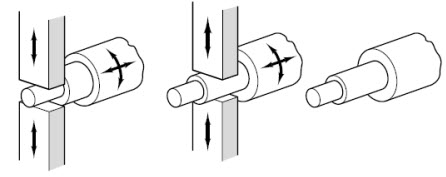
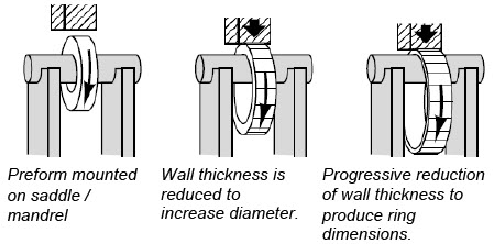
Figure 22: Multi-diameter shaft is obtained by cogging operation. Figure 23: Forging of a seamless (joint less) ring using cogging.
2.5.3 Edging
Edging is the process of gathering material into a region using a concave shaped open die. The process is called edging because it is usually carried out on the ends of the workpiece (Figure-24).
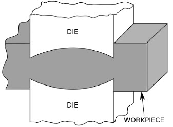
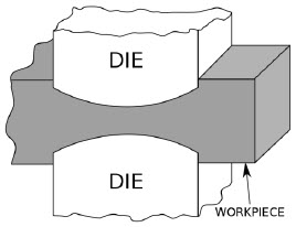
Figure 24: Edging Figure 25: Fullering
2.5.4 Fullering
Fullering is the process of reducing the cross-sectional area of a portion of the stock using a convex shaped die. The metal flow is outward and away from the centre of the fuller (Figure-25).
2.5.5 Blocking
Blocking stage makes the metal to approximately final shape, with generous corner and fillet radii (Figure-26).
2.5.6 Finishing
Finisher die imparts final shape and size, after which the flash is trimmed from the part (Figure-26).
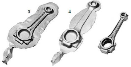
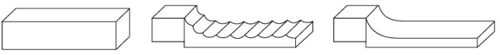
Edging Fullering Blocking Finisher Final product with flash is trimmed off
Figure 26: Steps followed in forging of Connecting Rod
2.6 Types of forging process on the basis of method of application of force
The different types of forging operations are:
(i) Hand forging,
(ii) Drop forging,
(iii) Press forging, and
2.6.1 Hand forging
The hand forging process consists of forming the desired shape of a heated metal by applying repeated blows of a hand held hammer. A flat die or an anvil is used. The desired shape of the metal piece is maintained by the smith during the forging process as the desired length and cross-section are adjusted manually by positioning and turning the part on the flat surface of the anvil. While hammering, tongs holds the red hot metal and a well-rounded chisel shaped edge, called fuller, and is used to draw out the metal. Fuller is held on the metal by a helper while the smith strikes the metal with a hammer. The quality of the forging is wholly dependent on the skill of the smith.
Applications: Only simple shapes can be hand forged. Horseshoes are hand forged and fitted to the hooves of the horse. Figure-27 illustrates a hand forging operation.
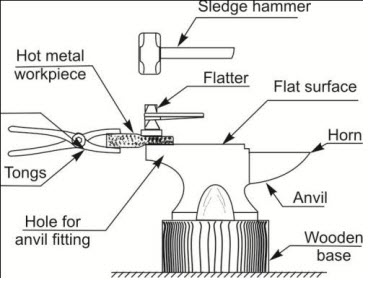
Figure 27: Hand forging operation
The tools used by a blacksmith include: anvil, swage block, hammers, tongs, swages fullers, and flatters. The shop where hand forging is carried out is called a smithy shop.
Hand forging is explained in detail in separate lesson-4 (Smithy).
2.6.2 Drop forging
Drop forging is a mechanized form of the black smith's hammer. In drop forge a massive weight is raised and made to fall freely. Dies are made in sets or halves; one half of the die is attached to ram and the other to a stationary anvil. The drop hammer uses compressed air or steam to lift the ram and lets it fall by gravity. The ram is lifted by a steel rod connecting it to a piston. In drop forging, from bar to final shape of the forged product is achieved in a number of steps by repeated blows of the dies contain impressions. Figure-28 & 29 illustrates a drop forging operation using a hydraulic hammer. During drop forging, a greater amount of energy is absorbed by the machine and foundation and the process is therefore not considered economical. Drop forging is very noisy and the shock of impact is difficult to isolate. In drop forging operations, the machine and foundation absorb much of the impact of the drop hammer.
Equipment: Gravity drop hammers
Application: Drop hammers are the choice for work pieces made of steel, aluminum alloys and brasses and bronzes.
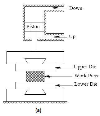
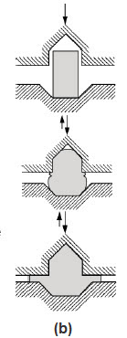
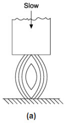
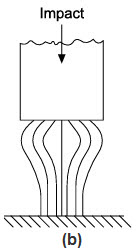
Figure 28: (a) Drop forging setup & (b) in drop forging series of blows are applied in order to obtain final shape.
Figure 29: (a) In Press forging uniform deformation (b) Drop forging non-uniform deformation
2.6.3 Press Forging
Press forging is done in presses rather than with hammers. In press forging a slow squeezing action is used to transfer a great amount of compressive force to the workpiece. Unlike an open-die forging where multiple blows are required to transfer the required energy to the material being forged, press forging process is more accurate as ram stick to the die impression more rigidly and transfers the force uniformly & gradually to the bulk of the material giving time for the metal to flow as it is pressed. This results in uniform material properties. The construction of the press is similar to the one given in Figure-28. Press forging is considerably a quieter operation than drop forging. Also greater portion of the total energy is transmitted to the metal than in a drop hammer.
Application: It is the choice for work pieces made of aluminum, magnesium, beryllium alloys, bronzes and brass.
2.7 Miscellaneous forging processes
2.7.1 Coining
It is a closed die forging process used mainly for minting coins and making of jewelry. In order to produce fine details on the work material the pressures required are as large as five or six times the strength of the material. Lubricants are not employed in this process because they can get entrapped in the die cavities and, being incompressible, prevent the full reproduction of fine details of the die.
Equipment: Presses and hammers.
Applications: Metallic coins; decorative items, such as patterned tableware, medallions and metal buttons; sizing of automobile and aircraft engine components.
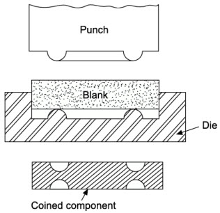
Figure 30: Coining process
2.7.2 Rotary Swaging
Rotary swaging is the application of forging process for shaping round bars, tubes in which the diameter of a rod or a tube is reduced. In rotary swaging process workpiece is held stationary and the dies rotate rapidly in a housing, the dies strike the workpiece at a rate as high as 10 - 20 strokes per second. The process is shown in figure 31. When compared to other methods of forging, production rate is high in rotary forging. The maximum diameter of work piece that can be swaged is limited to about 150 mm; work pieces as small as 0.5 mm diameter have been swaged. Swaging is a noisy operation.
Equipment: Rotary forging presses.
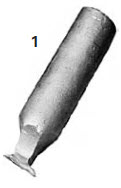
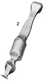
Applications: Screwdriver blades, box spanners and soldering iron tips are typical examples of swaged products. Figure 32-36 shows products made by swaging.
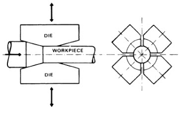
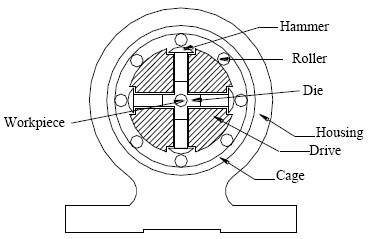
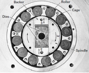
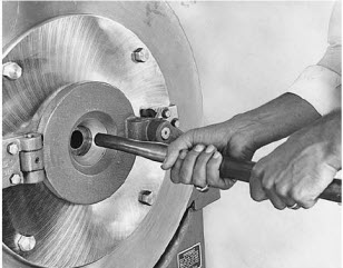
Figure 31: Rotary swaging process, Tube being reduced in a rotary swaging machine, Basic components and motions of a rotary swaging machine. When the cage is rotated, hammers come in contact with rollers. The moment when it comes in contact with the rollers, it gives blows on the workpiece through dies. The dies reciprocate with a high frequency, thereby deforming the workpiece to conform to the shape of the dies used.
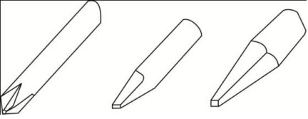
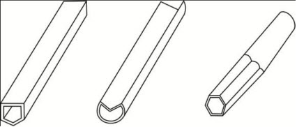
Figure 32: Solid parts made by swaging Figure 33: Hollow parts made by swaging
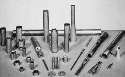
Figure 34: A variety of swaged parts, some with internal details
In tube swaging, the tube thickness and / or internal diameter of tube can be controlled with the use of internal mandrels. Also internally shaped tubes can be swaged by using shaped mandrels. Figure 35 shows the process.
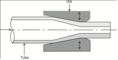
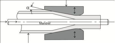
Figure 35 (a): Swaging of tubes without a mandrel Figure 35 (b): Swaging with a mandrel (Wall thickness is more in the die gap. The final wall thickness of the tube depends on the mandrel diameter)

Figure 35 (c): Examples of cross-sections of tubes produced by swaging on shaped mandrels

Figure 36: Steps followed in hot-swaging a tube to form the end (neck) of a pressurized gas cylinder
2.7.3 Orbital forging
A typical rotary forging process (sometimes called orbital forging) makes use of two dies to deform only a small portion of the workpiece at a time, and the process continues till whole of the workpiece is deformed, one portion after the other. The axis of upper die is tilted to a small angle with respect to the lower die, figure 37. The inclined upper die rotates around the workpiece in such a way that only a small area of the die is in contact with workpiece at any time. The lower die, however, is kept in horizontal position and rotates at the same speed as the upper die.
Equipment: Orbital forging presses.
Application: Bevel gears, claw clutch parts, wheel disks with hubs, bearing rings, rings of various contours, bearing-end covers.
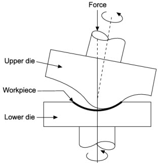
Figure 37: Orbital forging
2.7.4 Flashless forging (Precision forging)
In flashless forging, also known as precision or true closed-die forging, the metal is deformed in a cavity that provides total confinement, figure 38 (b). Accurate workpiece sizing is required since complete filling of the cavity must be ensured with no excess material. Accurate workpiece positioning is also necessary, along with good die design and control of lubrication. The major advantage of this approach is the elimination of the scrap generated during flash formation, an amount that is often between 20 and 45% of the starting material and minimum machining of the forged part is needed.
Equipment: Higher capacity presses are used.
Applications: Aluminium and magnesium alloys are particularly suitable for precision forging. Precision forged products are gears, connecting rods, housings, turbine blade.
(a) Flash can be observed in conventional closed die forging (b) At the end of forging, there is no flash in precision forging
Figure 38: Precision forging: comparison of closed die forging to precision forging of cylindrical billet.
2.7.5 Isothermal Die Forging
Isothermal die forging is also known as hot-die forging. In this process, dies are heated to the same temperature as that of the hot workpiece. When the workpiece is maintained hot (during forging), its low strength and high ductility are effectively maintained to help the forging operation. Forging forces are also low. The dies used are made of nickel or molybdenum alloys. The process is expensive and slow.
Equipment: Hydraulic presses
Application: Complex parts from titanium and super alloys and with good dimensional accuracy are forged by this process.
2.7.6 Roll Forging
This process is used to reduce the thickness of round or flat bar with the corresponding increase in length. When the rolls are in open position, the heated bar stock is placed between the rolls. With the rotation of rolls through half a revolution, the bar is progressively squeezed and shaped. The bar is then inserted between the next set of smaller grooves and the process is repeated till the desired shape and size are achieved.
Equipment: rolling mill that has two semi - cylindrical rolls that are slightly eccentric to the axis of rotation. Each roll has a series of shaped grooves on it.
Application: Leaf springs, axles, and levers.
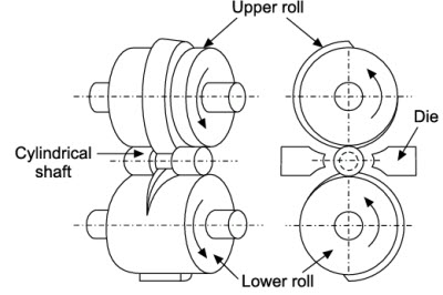
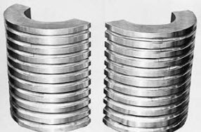
Figure 39: Roll Forging and product formed by roll forging
2.8 Dies used for forging
Since most forging operations are carried on elevated temperatures, dies should have
(a) high strength and toughness at high temperatures,
(b) hardenability and ability to harden uniformly,
(c) resistance to mechanical and thermal shocks and
(d) wear resistance.
The selection of die material is governed by size of forging and its shape complexity, number of forgings and forging temperature. Common die materials are tool and die steels containing chromium, nickel, molybdenum and vanadium.
2.9 Lubricants used in forging
A proper lubricant is necessary for making good forgings. The lubricant is useful in preventing sticking of the workpiece material with the die, and also acts as a thermal insulator to help reduce die wear. A wide variety of lubricants are used such as graphite and molybdenum disulphide used for hot forging dies. Lubricants affect and reduce forces required for forging. They also impart a thermal barrier between the hot workpiece and relatively cool die.
2.10 Defects in forgings
Defects in a forging may be due to following reasons:
(i) defective metal with a lot of inclusions of impurities or oxides,
(ii) faulty design of die,
(iii) improper upkeep of die (oxides may get deposited in pockets in the die),
(iv) development of internal stresses affecting the structure and strength of forging,
(v) oxides or scales not properly removed from the hot blank before forging and
(vi) oversize blank fed to the dies for forging.
Common forging defects are:
(i) Defective structure of forged piece due to defective base metal.
(ii) Incomplete forging (not up to correct dimensions) due to either less metal used for forging a part or the die may be defective.
(iii) Cracks at the corners of the forgings due to improper forging process.
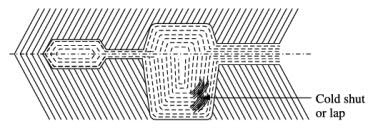
Surface cracking of forgings occurs due to excessive working of the workpiece surface at too low temperature or as a result of hot shortness.
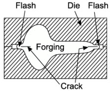
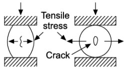
(a) Surface cracking (b) Cracking at the flash (c) Internal cracking
Figure: 40
Cracking at the flash of closed die forging is another defect since crack may penetrate into the forging when flash is trimmed off. Either increase the flash thickness or relocate the flash to less critical region of the forging.
Internal cracking the centre of the forging may be due to the development of secondary tensile stresses during forging. This can be reduced by proper die design.
Cracks in ribs may occur due to the use of oversize billet for.
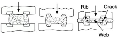
Figure 41: Cracks in ribs
(iv) Mismatched forgings due to faults in two halves of the die in working. Mismatch is caused by mis-alignment between the top and bottom dies.
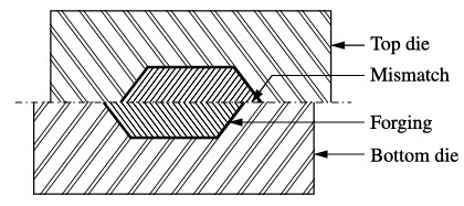
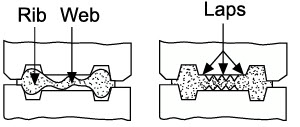
(a) Mismatched forgings (b) Cold shut or fold (c) Web buckles & laps are formed
Figure: 42
(v) Cold shut or fold is a discontinuity produced when two surfaces of the metal fold against each other without welding completely. The defect is caused due to sharp corners in the die cavity, excessive chilling or high friction.
(vi) Laps formed by web buckling are another defect in forgings. Thicker web should be used to avoid this defect.
(vii) Scale and oxidation of the surface of forging.
(viii) Oversize forging due to oversize dies.
Examples
Example 1: Explain the procedure of making the head of rivet by forging operation.
Solution: Step by step procedure to be followed in making the head of a rivet by forging operation is explained below:
(i) Keep the blank in the die as shown in figure 43(a) and position the kick out pin depending on the length of rivet required. Punch should have the negative shape of the rivet head as shown.
(ii) Apply force through the punch. At the end of the stroke, head is formed as shown in figure 43(b).
(iii) Now, remove the rivet by pushing the kickout pin.
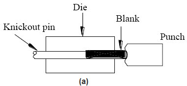
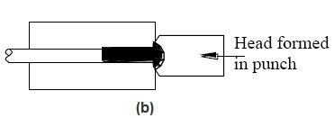
Figure 43: Rivet head formation
Example 2: Bolt is to be manufactured from a workpiece shown in figure-44 by forging operation. Explain the different stages involved in manufacturing.
Solution: The stepwise procedure for making bolt is explained below:
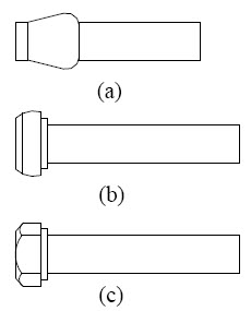
Figure 44: Different stages in forging a bolt head
First, gather the material at one end of the rod as shown in Figure 44 (a).
Produce round head as shown in Figure 44 (b).
Produce hexagonal head as shown in Figure 44 (c).
Terminal Questions
- Do you think it is possible to forge all materials? Justify your answer.
- List out any 5 components manufactured by forging other than given in the book.
- Explain with an example, where do you use (a) hand forging (b) drop forging and (c) press forging.
- Figure 45 shows a forging operation. Mention whether it is an open die forging or closed die forging. Justify your answer.
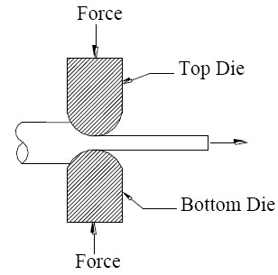
Figure 45: Figure for question 4
- In a forged component such as spanner, it is observed that the lettering on it is raised rather than being sunk. Why they are made that way? Explain.
- With the help of neat sketches, explain how a hexagonal nut can be manufactured from a cylindrical rod.
- How do you compare forged component with cast components?
- Mention any 3 differences between drop forging and press forging.
- Using Rotary swaging process, do you think it is possible to manufacture prismatic shape components? Justify your answer.
- Product shown in figure 46 is to be manufactured. Explain the different sequence involved in manufacturing the product.
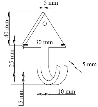
Figure 46: Figure for question 10
- Explain the sequence of operations involved in manufacturing the component shown in figure 47 (b) from the raw material shown in figure 47 (a).
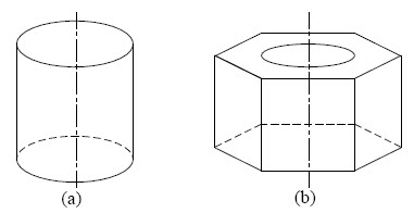
Figure 47: Figure for question 11
- You are supplied with a stock of MS rod having a dimension shown in figure 48 (a). It is required to obtain the product round headed bolt and square headed nut as shown in Figure 48 (b). List the process sequence involved.
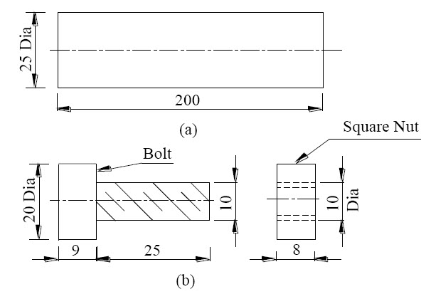
Figure 48: Figure for question 12
Table 3: Comparison of different forging materials
| Metal | Characteristic | Application |
|---|---|---|
| Aluminum | Readily forged Combines low density with good strength-to-weight ratio | Primarily for structural and engine applications in the aircraft. |
| Magnesium | Good strength-to-weight ratio, machinability | Usually employed at service temperatures lower than 500°F. |
| Copper, Brass, Bronze | Good electrical and thermal conductivity | Important for applications requiring corrosion resistance. |
| Carbon and Alloy Steels | Low material cost Good mechanical properties | Comprise the greatest volume of forgings produced for service applications up to 900°F. |
| Microalloy/ HSLA Steels | Low material cost Equivalent mechanical properties to many carbon and low-alloy steels | Various automotive and truck applications including crankshafts, connecting rods, yokes, pistons, suspension and steering components, spindles, hubs, and trunio |
| Stainless Steel | Corrosion-resistant | Used in pressure vessels, steam turbines, and many other applications in the chemical, food processing, petroleum, and hospital services industries. |
| Nickel-Base Superalloy | Creep-rupture strength Oxidation resistance | Structural shapes, turbine components, and fittings and valves. |
| Titanium | High strength Low density Excellent corrosion resistance | Aircraft-engine components and structurals, ship components, and valves and fittings in transportation and chemical industries. |
| Refractory Metals: molybdenum, tantalum, and tungsten and their alloys | Enhanced resistance to creep in high-thermal environments | High-temperature applications involving advanced chemical, electrical, and nuclear propulsion systems and flight vehicles. |