
To Study the Properties of Magic Tee and Determining the Scattering Parameters of Magic Tee.
Introduction
The Magic Tee is a four-port device & it is a combination of the E & H plane Tee. If the power is fed into arm 3 (H- arm), the electric field divides equally between arm 1 and 2 with same phase, and no electric field exists in arm 4. If the power is fed in arm 4 (E- arm), it divides equally into arm 1 and 2 but out of phase with no power to arm 3. Further, if the power is fed from arm 1 and 2, it is added in arm 3 (H-arm), and it is subtracted in E-arm, i.e., arm 4.
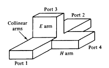
Fig. 1 Magic-Tee
The basic parameters to be measured for Magic Tee are defined below:
- Isolation: The isolation between E and H arms is defined as the ratio of the power supplied by the generator connected to the E-arm (port 4) to the power detected at H-arm (port 3) when side arms 1 and 2 are terminated in matched load.
Hence,
- Coupling Coefficient: It is defined as
Where α is attenuation / isolation in db when 'i' is input arm and 'j' is output arm.
Thus
Where Pi is the power delivered to arm i and Pj is power detected at j arm.
Component List
Klystron Power Supply
The klystron power supply provides the necessary high voltage and current to the klystron tube.Klystron Mount
The klystron mount securely holds the klystron tube in place during experiments.Klystron or Microwave Source
Serves as the signal generator, producing the microwave frequency signals that will be fed into the Magic Tee for analysis.Isolator Prevents any reflected signals from returning to the microwave source, protecting it from potential damage and ensuring stable signal flow in one direction.
Attenuator
Allows for precise control of the input power to the Magic Tee, enabling adjustments to study how variations in input power affect the S-parameters.Magic Tee
A four-port device that combines E-plane and H-plane functionalities. It is essential for splitting and combining signals, and it facilitates the measurement of S-parameters, including isolation and coupling.Detector Mount
Measures the power of the output signals from the Magic Tee, providing data needed to calculate the scattering parameters.VSWR Meter
Measures the Voltage Standing Wave Ratio (VSWR) to assess the efficiency of power transfer and to help identify mismatches in impedance at the ports.Frequency Meter
Measures the frequency of the microwave signals being transmitted through the Magic Tee, ensuring accurate characterization and analysis.Slotted Line
Visualizes standing wave patterns and measures the voltage standing wave ratio (VSWR) along a transmission line, aiding in the assessment of signal behavior through the Magic Tee.Matched Terminator
A matched terminator is connected to one of the ports of the Magic Tee that is not being used for measurements.
Block Diagram
For P1:
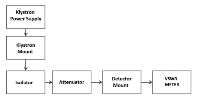
Fig. 2 Bench setup for recording P1 value
For P2:
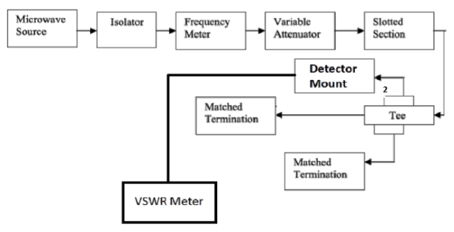
Fig. 3 Bench setup for recording P2 value
For P3:
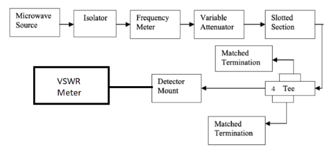
Fig. 4 Bench setup for recording P3 value