Performance measurement and analysis of isolated DC-DC flyback converter
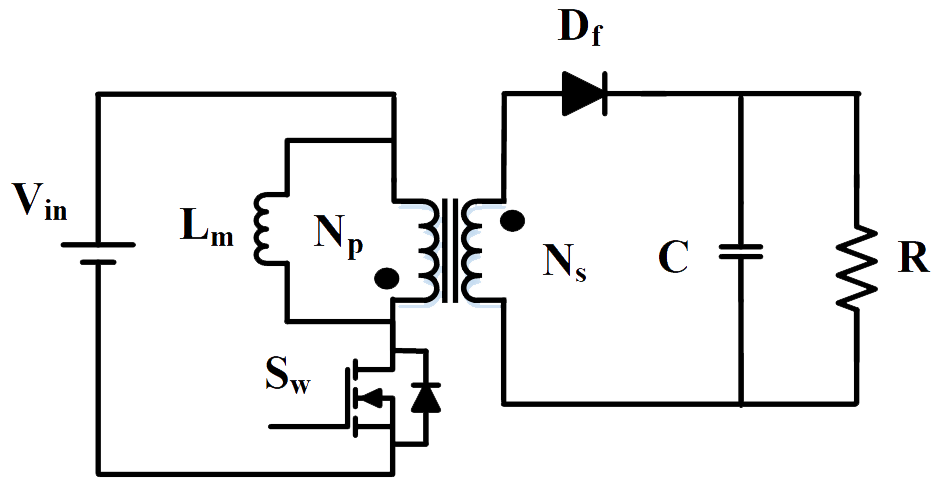
Answer the questions given below (refer Fig.2):

Fig. 2. Circuit diagram of flyback converter.
1. Choose the correct expression for inductor ripple current (∆iLm)::

Fig. 2. Circuit diagram of flyback converter.
1. Choose the correct expression for inductor ripple current (∆iLm)::
2. Find the load current when input current is 0.5 A and duty ratio-D is 0.7 with unity turns ratio
3. A flyback converter has ‘Vin’ as source voltage and ‘D’ is the duty ratio. Find the r.m.s value of output voltage with unity turns ratio
4. Which material is used to make the core of Flyback transformer
5. A flyback converter in continuous conduction mode converts 160 V DC to 3.3 V DC. If the duty cycle is 0.40, calculate the turns ratio of the transformer. Assume negligible voltage drop across switch and diode.
