
Heat Transfer by Natural Convection
Procedure
Apparatus
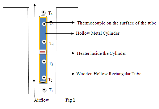
Figure 1: Description of the figure
Performing the Simulation:
Simulator Controls
1. Choose material - This can used to select the material for the metal cylinder.
2. Side of wooden box - Side of the outer wooden hollow rectangular box can be varied in cm.
3. Height of wooden box - Height of the outer wooden hollow rectangular box can be varied in cm.
4. Diameter of cylinder- Diameter of the vertical cylinder can be varied in cm.
5. Length of the cylinder - Length of the vertical cylinder can be varied in cm.
6. Thickness of cylinder - Thickness of the vertical cylinder can be varied in cm.
7. White knob - can be rotated by clicking the side arrows to adjust the voltage and corresponding current, which can be used to calculate input power.
8. Power On - click to start the experiment.
9. Temperature indicator - used to read the temperature at the positions of the various thermocouples. After a steady state is reached (when the timer shows 20 minutes), click the arrows on either side of the knob to read temperatures T1 to T6 in degrees Celsius.
Procedure for Simulation
1. Choose a particular material to carry out the experiment.
2. Choose the height and side of the wooden box with the box sliders.
3. Adjust the diameter, length and thickness of the cylinder using the cylinder sliders.
4. Apply a particular voltage and corresponding current using white knob in the simulator.
5. Using temperature indicator, note the values of T1, T2, T3, T4, T5 and T6 and, using the table and worksheet below, calculate the heat transfer coefficient and Nusselt number.
6. Click show result to check your calculations. You can also enter your data in the worksheet on the Simulator to check some of the intermediate quantities in the main calculations.
Procedure for Real lab
The procedure for a real lab is quite similar, except that the calculations can be extended to include heat loss from the cylinder by radiation, which is often not negligible. For example, at the highest temperatures seen in our simulation, the radiation heat loss would be comparable to the convection heat loss, so only about half the electrical power input would be lost by convection.
Calculations and Observations
Power input to the heater,
Area of heat transfer,
=Average temperature of the tube - Average temperature of the air
We hav , and by definition
and
Where k = 0.024 Wm-1K-1 is the thermal conductivity of air, and L is the length of the cylinder, set by the slider (be sure to convert cm to meters).
Result
Heat transfer coefficient h = ..........
Nusselt number N = .....................