Familiarization with general bread board.
Procedure
- Click on “Click Here” in Simulation tab.
- Read every slide carefully to know about Breadboard connections.
- For next slide click on > button and for previous slide click on < button.
Power supply connections
- Connect +5 V and ground terminals of the power supply to different power rails of one side of breadboard.
- Connect the power rails on both sides by using jumper wires.
- Connect horizontal rows by using jumper wires.

Fig. 1 A breadboard with power rail connections
- Thus, top and bottom rail sets of power rails become active which is shown by blue colour. Now, all holes of two sets of power rails are ready to use.
- As different components are placed over breadboard, all the holes which are internally connected become active and are shown in red colour.
Familiarise with components


Fig. 2 Components
Series connections on Breadboard
- Click on the Component button to place components on the table.
- Make connections as per the circuit diagram or connection table.
- All five holes in a vertical column are electrically connected; hence two legs of LED and resistance should be in different vertical columns.

Fig. 3 Circuit diagram for series connections of LEDs.

Table 1: Connection table for series connection
- Click on Check Connections button. If connections are right, click on ‘OK’, then Simulation will become active.
- Observe output i.e. all LEDs will be ON.
- Now select Parallel connection.
Parallel connections on Breadboard
- Click on the Component button to place components on the table.
- Make connections as per the circuit diagram or connection table.

Fig. 4 Circuit diagram for parallel connections of LEDs.
Table 2: Connection table for parallel connection

- Click on Check Connections button. If connections are right, click on ‘OK’, then Simulation will become active.
- Observe output i.e. all LEDs will be ON.
- Click on > button for next slide.
Familiarisation with Logic Gate connections of an IC 7432
- Click on the Component button to place components on the table.


Fig. 6 Components
- Note that IC’s half circle is on the left side on the breadboard.
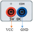
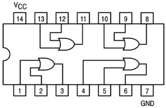
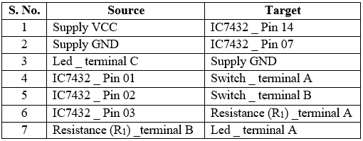
- Connect pin 14 to the power supply (+5 V) and pin 7 to ground (0 V). (Refer pin diagram of IC 7432).

Fig. 5 Pin Diagram of IC 7432
Table 3: Connection table

- Connect pin 1 and pin 2 to toggle switches A and B respectively.
- Connect corresponding output terminal (pin 3) to resistance (220 Ω). The other end of resistance is connected to positive (+) terminal of LED.
- Connect negative (–) terminal of the LED to ground.
- Click on Check Connections button. If connections are right, click on ‘OK’, then Simulation will become active.
- Apply different combinations (0,0), (0,1), (1,0) and (1,1) to input terminals of one gate (say pins 1 and 2) by using toggle switches A and B.
- Observe the corresponding output on the LED.
- Fill the observed values in the Truth Table.
- Verify the Truth Table of 'OR' gate from the experimental results by clicking on Check button, if outputs are correct then click on OK.
- Repeat steps 4 to 11 for different gates of the IC.
- Click on the Reset button to reset the page.
