Connection and measurement of power consumption of a fluorescent lamp(tube light).
Fluorescent lamp constitutes a glass tube whose inside is coated with
a fluorescent powder. When the two filaments of the lamp are maintained at potential
difference sufficient enough to produce electric discharge through the gap, then
electron are emitted from one electrode and move towards the other electrodes. In
the mean time, these electrons collide with the fluorescent coating and emit cool
light. In most fluorescent lamp, a mixture of argon and mercury gas contained in a
glass tube is stimulated by an electric current, producing ultraviolet ray. These rays
strike fluorescent phosphorous coating on the interior surface of the bulb.
Unfortunately a fluorescent lamp can t just work as is case of incandescent lamp.
The main reason is that it is normally takes a voltage greater than the typical line
voltage to start. It requires several hundreds of volts (V).
A fluorescent lamp is a sealed glass tube with two electrodes at its two ends. The
fluorescent lamp circuit consists of a choke coil, a starter and a fluorescent tube. The
length of the commonly used fluorescent tube is 100 cm; its power rating is nearly 40 W,
230V and 50 Hz. The tube is filled with argon and a drop of mercury. When the supply is
switched on, the current heats the filaments and initiates emission of electrons. After one
or two seconds, the starter circuit opens and makes the choke to induce a momentary
high voltage surge across the two filaments
Starter: Special kind of switch that consists of a small gas-discharge tube, containing
neon or argon in parallel with a normally open bi-metallic switch. It is connected in parallel
with the fluorescent lamp. When a voltage is applied, discharge is generated within the
starter tube, heating and bending the bimetallic electrode, causing the switch contacts to
close. Consequently, the discharge disappears and within a second, bimetallic strip
reverts back to its normal position causing the switch contacts to open.
Choke Coil: Choke Coil is a high-inductance coil which must be used in series with
fluorescent lamp for two reasons. During starting time, it generates a high voltage pulse
across the tube when the starter's contacts open. That pulse causes the gas in the tube
to ionize and provide a low-resistance path between the two electrodes of the lamp.
During running time, it limits the lamp current to prevent the lamp from being short
circuited.
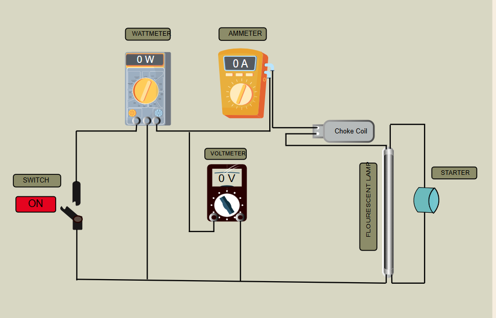
Circuit diagram shown below is the connection diagram of a fluorescent lamp, starter and
choke coil. In this circuit when the 1-phase supply is applied then the measurement of
power consumption of fluorescent lamp is done with the help of wattmeter. Finally with the help of wattmeter, ammeter and voltmeter the power factor of circuit is calculated