
Finite state machines 
Procedure
Finite State Machine
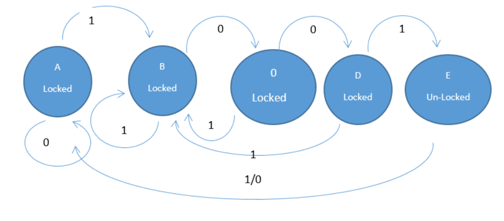
Here we have design a finite state machine for a simple combinational lock where the passcode is 4 bit binary number 1001. To design a state machine for a 4-bit combinational lock with the passcode 1001, we can create a sequential circuit that tracks the input sequence one bit at a time. This can be implemented as a Moore machine, where the output depends only on the current state. The machine will have a series of states corresponding to the correct sequence fragments detected so far. The state diagram is as follows.
State diagram
State machine design specifications
- Inputs: A single binary input, X, where each bit of the passcode is entered sequentially. A Reset signal is also included to return the system to its initial state at any time.
- Outputs: A single binary output, Unlock, which becomes 1 only when the full, correct sequence 1001 has been entered.
- States: The machine requires one state for each bit of the passcode plus an initial reset state. We will define five states:
- State A (Reset): The initial state. The system is waiting for the first correct bit of the passcode. The Unlock output is 0.
- State B (Got '1'): The first bit, a 1, has been correctly entered.
- State C (Got '10'): The first two bits, 10, have been correctly entered.
- State D (Got '100'): The first three bits, 100, have been correctly entered.
- State E (Unlocked): The full sequence 1001 has been entered. The Unlock output is 1
Here is the State Transition Table for above combinational lock.
| Present State | Input (X) | Next State | Output (Unlock) |
|---|---|---|---|
| A | 0 | A | 0 |
| A | 1 | B | 0 |
| B | 0 | C | 0 |
| B | 1 | B | 0 |
| C | 0 | D | 0 |
| C | 1 | B | 0 |
| D | 0 | A | 0 |
| D | 1 | E | 0 |
| E | 0 | A | 1 |
| E | 1 | B | 1 |
| All states | Reset = 1 | A | 0 |
Explanation of state transitions
From State A (Reset): The lock is waiting for the first bit.
- Input X=1: The first correct bit is received. Transition to State B.
- Input X=0: An incorrect bit is received. Remain in State A.
From State B (Got '1'): The first 1 is received.
- Input X=0: The second correct bit is received. Transition to State B.
- Input X=1: An incorrect bit is received. However, this 1 could be the start of a new sequence. Stay in State B, as the new potential sequence (1) is now correctly in place. This is an overlapping sequence detection feature.
From State C (Got '10'): The sequence 10 is received.
- Input X=0: The third correct bit is received. Transition to State D.
- Input X=1: An incorrect bit is received. However, this 1 could be the start of a new sequence. Go back to State B.
From State D (Got '100'): The sequence 100 is received.
- Input X=1: The fourth and final correct bit is received. The lock is opened. Transition to State E.
- Input X=0: An incorrect bit is received. The sequence is broken. Reset to State A.
From State E (Unlocked): The lock is open.
- Input Reset=1 or X=0: Any subsequent input or an explicit Reset signal will re-lock the machine. Return to State A.
- Input X=1: This input could be the start of a new sequence (1). Go back to State B. This allows for re-locking with a specific input while still handling overlapping patterns if the user were to try a different sequence.
Simulation
Simulation of the above combination lock has been shown below with the help of D Flip Flop and 4 bit AND gate.
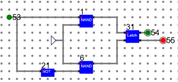
The D Flip Flop is designed as below:
- Design Latch circuit and make a component say ‘Latch’.
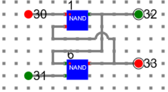
- Using the latch, design a D-FF and make a component as shown below.
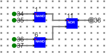
4 input AND gate is designed as below.
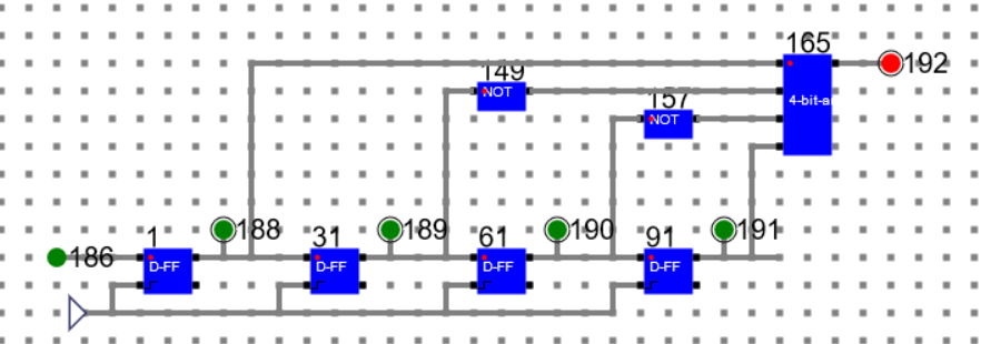
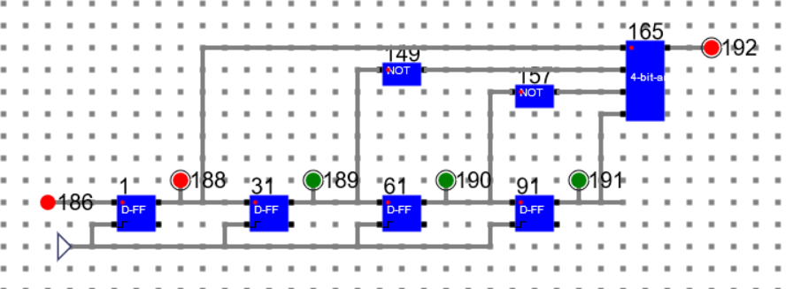
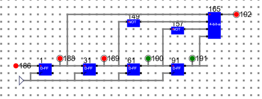
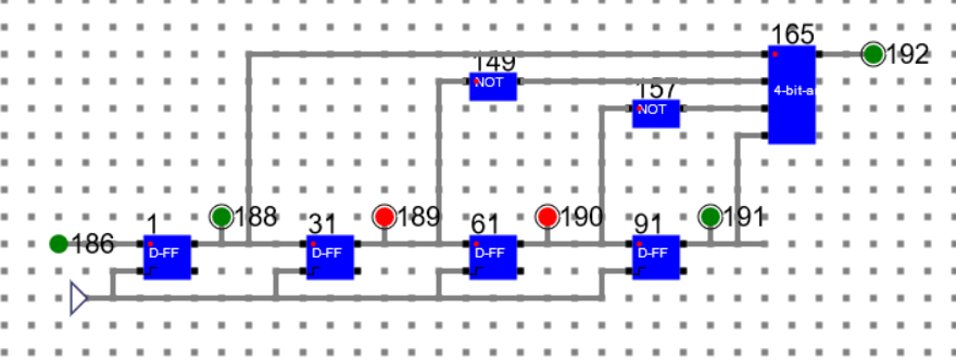
Circuit and Simulation of the combinational lock is as below
186: Input, 192: Output
State 1: Data: 1111 State: Locked
State 2: Data: 0111 State: Locked
State 3: Data: 0011 State: Locked
State 4: Data: 1001 State: Un-Locked
Step 5: Data: 0100 State: Locked

Manual
- Refer the simulator manual on how to design the circuit
- Manual --> Click Here