
Demonstration of Exoelectrogenesis using Caulobacter Crescentus
Procedure
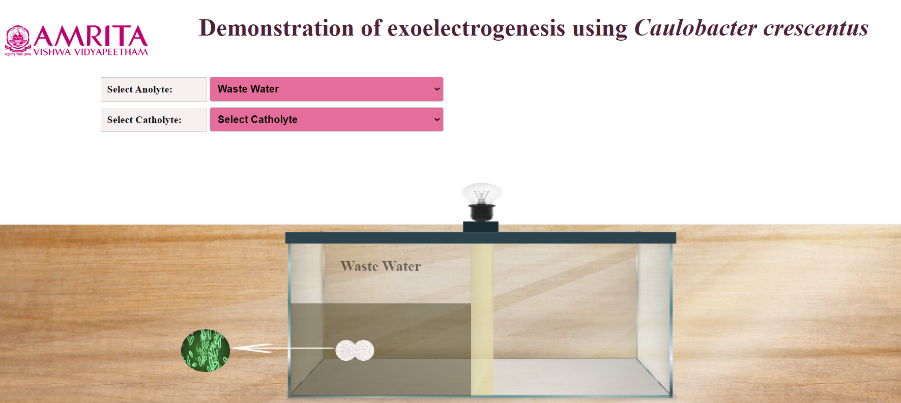
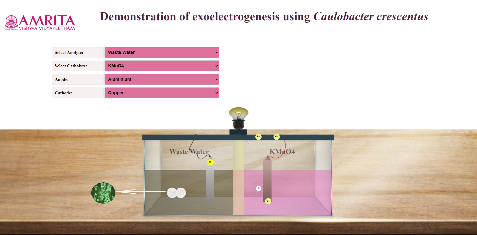
- Users can open the simulator window. In the simulator window, input parameters Anolyte and Catholyte were provided. The design of a microbial fuel cell is also displayed. The anodic chamber (anolyte) is filled with wastewater.
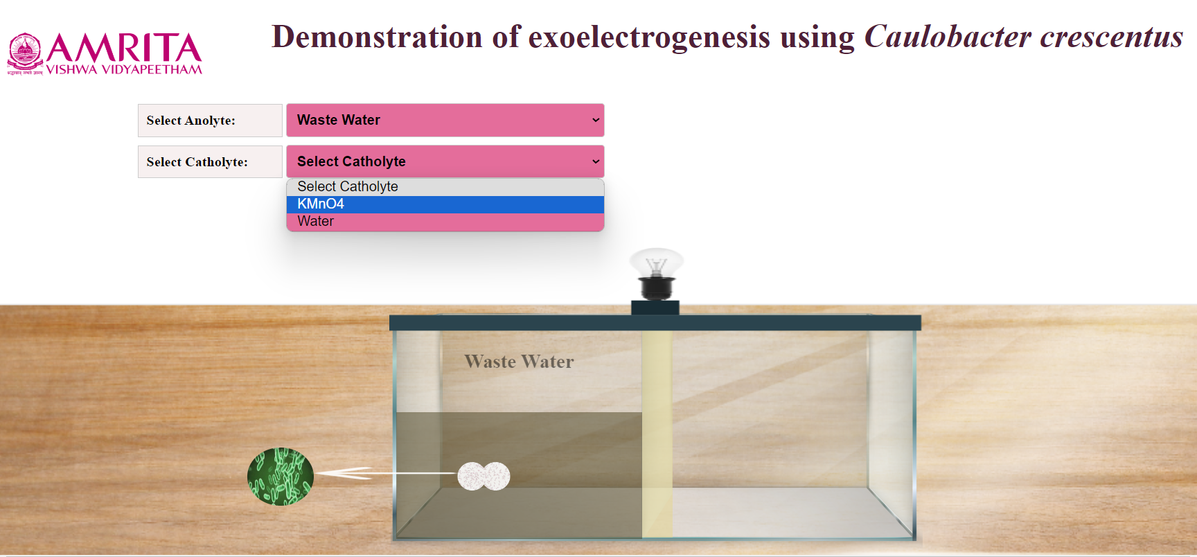
2. Users can choose either KMnO4 or Water as Catholyte.
3. Here, KMnO4 is chosen as Catholyte. At the same time, users can select Anode and Cathode.
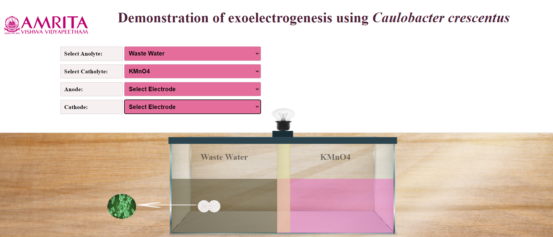
4. As the anode, Aluminium, Manganese, Carbon, Graphite, and Stainless Steel were provided as options, and Copper and graphite were provided as options as Cathode. Users can select anode and cathode according to their choice.
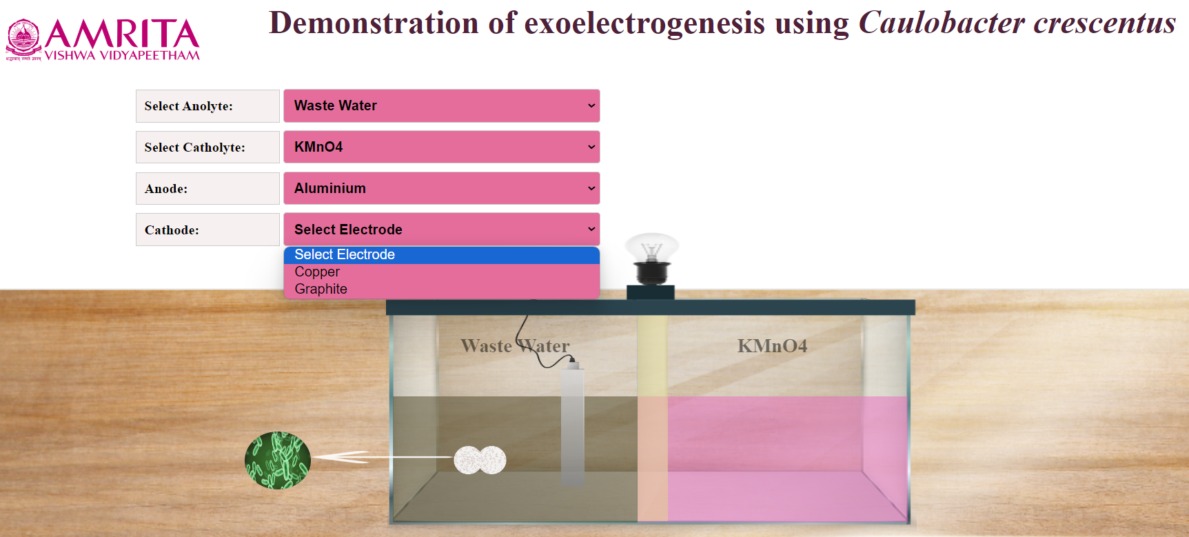
Here, Anolyte is Wastewater, Catholyte is KMnO4, Anode is Aluminum and Cathode is Copper. After finishing the connections, the Caulobacter crescentus, exoelectrogen added in the wastewater (anolyte) consume the substrate and start producing current (milli ampere). Caulobacter crescentus releases electron shuttles extracellularly facilitating electron transfer from bacteria to the electrodes. Caulobacter crescentus also get contact with the anode enhancing electron transfer efficiency. The electron transfer to the circuit is shown as e- . This transfer of electrons are responsible for producing electrical energy which was shown as electric bulb glow in the simulator.
At the same time H+ ions (protons) , at the anode are transferred to the cathode through the PEM where they combine with existing oxygen and electrons to form water molecule in the cathodic chamber.
The process will continue until Caulobacter crescentus consumes the whole substrate provided in the anodic chamber.