
Digital Comparator 
Procedure
- To draw any diagram in the simulator please follow the manual given in manual section.
- Step 1. Design a one bit comparator.
- A one-bit comparator has been designed in the simulator using basic AND, NOT, and NOR gates as shown below.
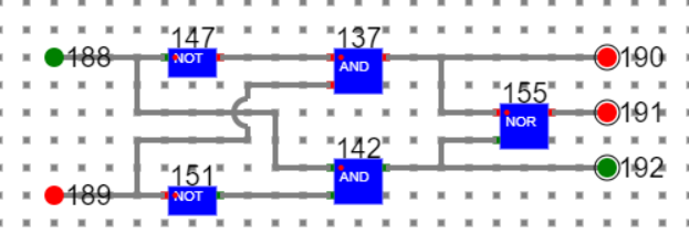
where
188, 189: Input Bits
190 high means A < B,
191 high means A = B,
192 high means A > B
Save this as a component say 1BIT-CMP.
Step 2. Design 4 bit comparator
- A> Design a 4 input ‘AND’ gate like below.
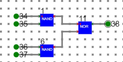
B> Save it as a component say 4IN-AND
C> Design a 4 input ‘OR’ gate like below. This has used one 3 input ‘OR’ gate designed before and a basic ‘OR’ gate readily available in the simulator.
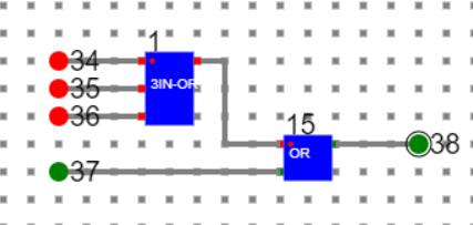
D> Save it as a component say 4IN-OR.
E> Now design a 4 bit comparator with the help of four 1 bit comparator, one 4 input ‘AND’ gate and two 4 input ‘OR’ as shown below.
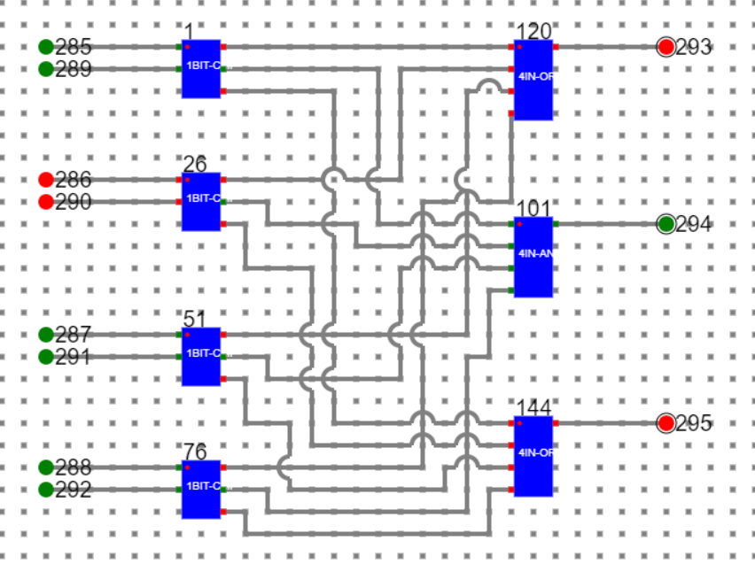
1, 26, 51, 76: 1BIT-Comparator
120, 144: 4 Input-OR
101: 4 input-AND
Number1: 285 (LSB), 286, 287, 288 (MSB)
Number2: 289 (LSB), 290, 291, 292 (MSB)
293 is high: Number1 < Number2
294 is high: Number1 = Number2
295 is high: Number1 > Number2
Manual
- Follow the below manual and perform the experiment
- Manual --> Click Here