
Digital to analog converter
Procedure
- 3 bit Binary Weighted Resistors
- Connect the components as mentioned below: L1-L5, L4-L6, L3-L5.(For eg. click on 1 and then drag to 5 and so on.)
- Click on 'Check Connection' button to check the connections.
- If connected wrong, click on the wrong connection. Else click on 'Delete all connection' button to erase all the connections.
- Set the Resistance (R) value (1 Kohm - 10 Kohm).
- Set the Feedback Resistance (Rf) value same as the Resistance (R) .
- Set input voltage (Vin).
- The IC is given proper bias of +12V and -12V to VCC and VEE respectively.
- Intially B2B1B0 are set to 000.(B2B1B0 are 3 bit input)
- Now note the output voltage and click on 'Add to table' button.
- Change the B2B1B0 and note the output voltage and click on 'Add to table' button.
- Repeat the experiment for another set of resistance value.
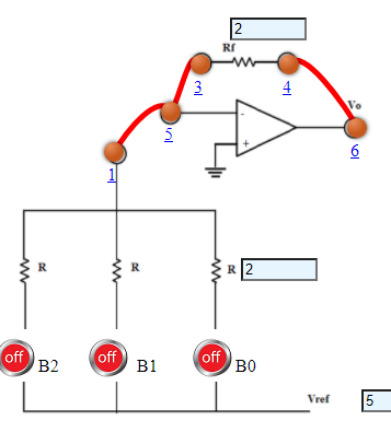
Fig 1: 3 bit Binary Weighted Resistors
- 4 bit Binary Weighted Resistors
- Connect the components as mentioned below: L1-L5, L4-L6, L3-L5.(For eg. click on 1 and then drag to 5 and so on.)
- Click on 'Check Connection' button to check the connections.
- If connected wrong, click on the wrong connection. Else click on 'Delete all connection' button to erase all the connections.
- Set the Resistance (R) value (1 Kohm - 10 Kohm).
- Set the Feedback Resistance (Rf) value same as the Resistance (R) .
- Set input voltage (Vin).
- The IC is given proper bias of +12V and -12V to VCC and VEE respectively.
- Intially B3B2B1B0 are set to 0000.(B3B2B1B0 are 4 bit input)
- Now note the output voltage and click on 'Add to table' button.
- Change the B3B2B1B0 and note the output voltage and click on 'Add to table' button.
- Repeat the experiment for another set of resistance value.
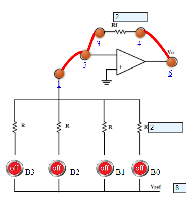
Fig 2: 4 bit Binary Weighted Resistors
- 4 bit Binary Ladder
- Connect the components as mentioned below: L1-L5, L4-L6, L3-L5, L9-L12.(For eg. click on 1 and then drag to 5 and so on.)
- Click on 'Check Connection' button to check the connections.
- If connected wrong, click on the wrong connection. Else click on 'Delete all connection' button to erase all the connections.
- Set the Resistance (R) value (1 Kohm - 10 Kohm).
- Set the Feedback Resistance (Rf) value same as the Resistance (R) .
- Set input voltage (Vin).
- The IC is given proper bias of +12V and -12V to VCC and VEE respectively.
- Intially B3B2B1B0 are set to 0000.(B3B2B1B0 are 4 bit input)
- . Now note the output voltage and click on 'Add to table' button.
- Change the B3B2B1B0 and note the output voltage and click on 'Add to table' button.
- Repeat the experiment for another set of resistance value.
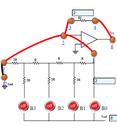
Fig 3: 4 bit Binary Ladder