
To verify De-Morgan's theorems.
Procedure
- Under Simulation, click Theorem 1 or Theorem 2.
Familiarise with components


")
Fig. 1 Components
1st Theorem :-
L.H.S. term for De-Morgan’s 1st theorem, i.e (A + B)' :–
- Click on the Component button to place components on the table.
- Make connections as per the circuit diagram and pin diagrams of ICs or according to connection table.
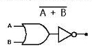
Fig. 2 Circuit diagram of (A + B)'
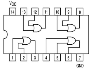
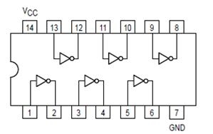
Fig. 3 Pin diagram of IC 7432 Fig. 4 Pin diagram of IC 7404
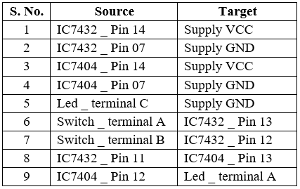
Table 1: Connection table for (A + B)'
- Click on Check Connections button. If connections are right, click on ‘OK’, then Simulation will become active.
- Provide the input by clicking toggle switches A and B.
- Fill the observed values in the Truth Table.
- Verify Truth Table by clicking on Check button, if outputs are correct then click on OK.
- Click on the Result button provided below the table.
R.H.S. term for De-Morgan’s 1st theorem, i.e A'B' :–
- Click on the Component button to place components on the table.
- Make connections as per the circuit diagram and pin diagrams of ICs or according to connection table.
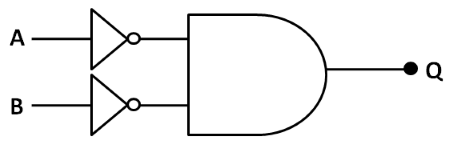
Fig. 5 Circuit diagram of A'.B'

Fig. 6 Pin diagram of IC 7408
Fig. 7 Pin diagram of IC 7404
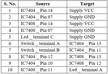
Table 2: Connection table for A'.B'
- Click on Check Connections button. If connections are right, click on ‘OK’, then Simulation will become active.
- Provide the input by clicking toggle switches A and B.
- Fill the observed values in the Truth Table.
- Verify Truth Table by clicking on Check button, if outputs are correct then click on OK.
- Click on the Result button provided below the table.
2nd Theorem :-
L.H.S. term for De-Morgan’s 2nd theorem, i.e (A.B)' :–
- Click on the Component button to place components on the table.
- Make connections as per the circuit diagram and pin diagrams of ICs or according to connection table.
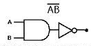
Fig. 8 Circuit diagram of (A.B)'
Fig. 9 Pin diagram of IC 7408
Fig. 10 Pin diagram of IC 7404
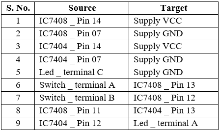
Table 3: Connection table for (A.B)'
- Click on Check Connections button. If connections are right, click on ‘OK’, then Simulation will become active.
- Provide the input by clicking toggle switches A and B.
- Fill the observed values in the Truth Table.
- Verify Truth Table by clicking on Check button, if outputs are correct then click on OK.
- Click on the Result button provided below the table.
R.H.S. term for De-Morgan’s 2nd theorem, i.e (A' + B') :–
- Click on the Component button to place components on the table.
- Make connections as per the circuit diagram and pin diagrams of ICs or according to connection table.
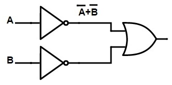
Fig. 11 Circuit diagram of (A' + B')
Fig. 12 Pin diagram of IC 7432
Fig. 13 Pin diagram of IC 7404
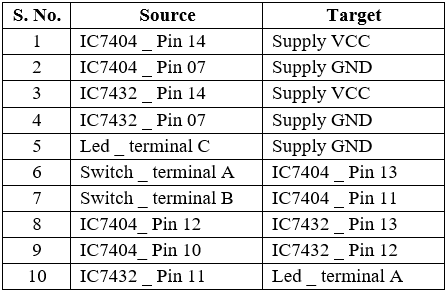
Table 4: Connection table for (A' + B')
- Click on Check Connections button. If connections are right, click on ‘OK’, then Simulation will become active.
- Provide the input by clicking toggle switches A and B.
- Fill the observed values in the Truth Table.
- Verify Truth Table by clicking on Check button, if outputs are correct then click on OK.
- Click on the Result button provided below the table.