
Speed Control of DC motor by field resistance control
STEP 1: Make connections as per the instructions given below:
| From | A | B | B | B | Q | G | E | F | H | I | C |
| To | P | K | Y | J | L | R | M | D | I | C | H |
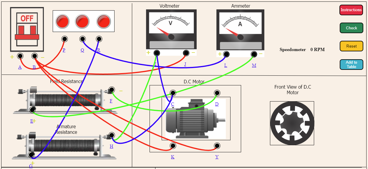
STEP 2: Then Check the connections by clicking on "Check" Button.
STEP 3: If it shows alert "Incorrect Corrections" then click on node number to detach the wire or press reset button and make connection again.
STEP 4: If it shows alert "Correct Connections" then Turn On the MCB.
STEP 5: Then set the Voltmeter first with the help of the second slider.
STEP 6: Now, move the first slider to get corresponding values of Ammeter and Speedometer.
STEP 7: Press the "Add to table" button to insert the values in the table.
STEP 8: After inserting values on table click on "Plot graph" to get your required graph.
STEP 9: Click on "Print" button to print the webpage.
STEP 10: Click on "Reset" button to reset the webpage.