Frequency Response of CS Amplifier
Procedure
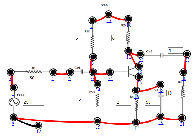
- Connect the components as mentioned below: L1-L3, L4-L5, L6-L8, L6-L14, L6-L24, L7-L13, L9-L15, L10-L13, L11-L22, L15-L17, L16-L25, L17-L19, L18-L16, L19-L21, L20-L23, L26-L11, L12-L9.(For eg. click on 1 and then drag to 3 and so on.)
- Click on 'Check Connection' button to check the connections.
- If connected wrong, click on the wrong connection. Else click on 'Delete all connection' button to erase all the connections.
- The Input voltage (Vin) is set to 50mV at 1 KHz frequency.
- Keeping source voltage constant, vary the frequency from 50 Hz in regular steps.
- Set Input Resistance (RI)=50Ω.
- Set Drain Resistance (RD)=8 kΩ, Set Source Resistance (RS)=2 kΩ, Set Load Resistance (RL)=10 kΩ.
- Set Gate Resistance1 (RG1)=5 MΩ, Set Gate Resistance2 (RG2)=5 MΩ.
- Set Coupling Capacitor1(CC1)=1 μF, Set Coupling Capacitor2 (CC2) =1 μF, Set Bypass Capacitance (CS)=50μF.
- Click on "Add to Table" button to add the readings to the table.
- Vary the Frequency by keeping the resistances constant.
- Click on "Plot" button to plot the Magnitude graph of the CS Amplifier, Frequency(Hz) along X-axis and Magnitude(dB) along Y-axis.
- Click on "Clear" button to take another set of readings.