Covert Channels and Information Leakage
Introduction to Covert Channels
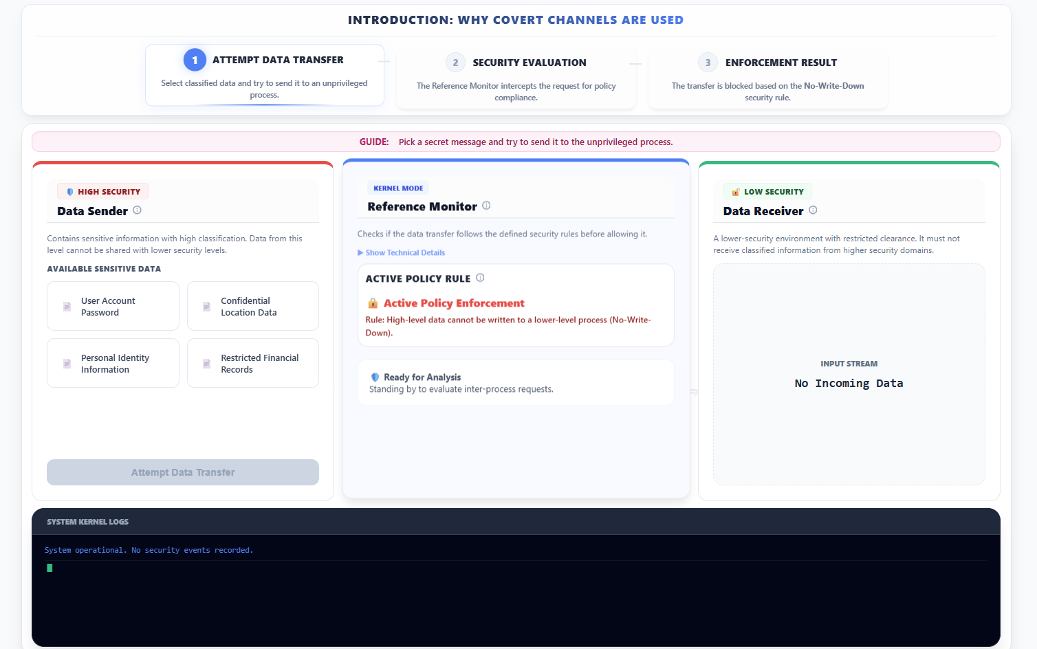
- Observe the introduction: Why Covert Channels are Used panel which outlines the sequence of attempting a direct but restricted data transfer.
- In the left panel (🛡️ HIGH SECURITY - Data Sender):
- Select a piece of sensitive data (e.g., "User Account Password") from the list.
- Click Attempt Data Transfer.
- In the center panel (Reference Monitor - KERNEL MODE):
- Observe that the system evaluates the request against the Mandatory Access Control (MAC) policy.
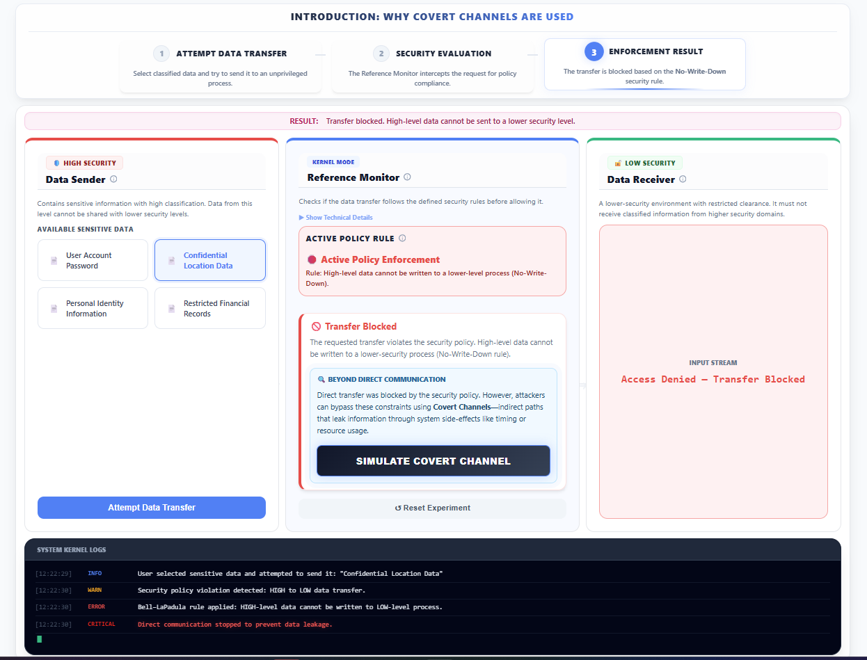
- Note that the No-Write-Down rule (Bell-LaPadula model) is enforced, and the request is blocked.
- In the right panel (🔓 LOW SECURITY - Data Receiver):
- Observe that the Input Stream displays Access Denied — Transfer Blocked, indicating that the primary transfer mechanism is controlled.
- At the bottom section of the screen, review the System Kernel Logs to observe how the kernel records the security violation.
- Click Simulate Covert Channel to proceed to specialized simulations for bypassing these direct controls.
1. Storage Covert Channel
- In the top navigation area, select the Storage Channel option.
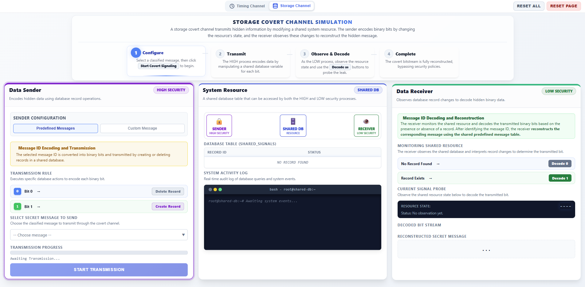
Step 1: Sender Phase – Configure and Start Transmission
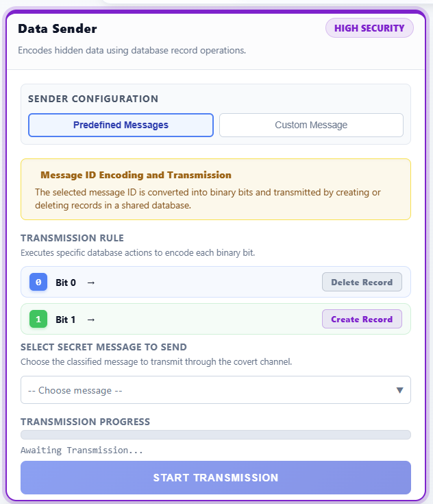
- In the left panel (DATA SENDER - HIGH SECURITY), configure the transmission:
- Message Type: Choose between Predefined Messages (select a classified ID like M1, M2) or Custom Message (enter your own secret text).
- Observe the Binary Conversion display, which shows how the message is converted into a sequence of bits (0s and 1s).
- Review the Transmission Rule:
- Bit 1: The sender executes an
INSERTquery to add a record to the shared database. - Bit 0: The sender executes a
DELETEquery to remove the record from the shared database.
- Bit 1: The sender executes an
- Click START TRANSMISSION to begin leaking the data bit-by-bit.
Step 2: Observation Phase – Monitor Shared Resource
- In the center panel (SYSTEM RESOURCE - SHARED DB):
- Observe the Database Table visualization. A row appearing indicates a Bit 1 signal, while an empty table indicates a Bit 0 signal.
- Monitor the System Activity Log (bash terminal) to see the real-time SQL queries (
INSERT/DELETE) being executed by the HIGH process.
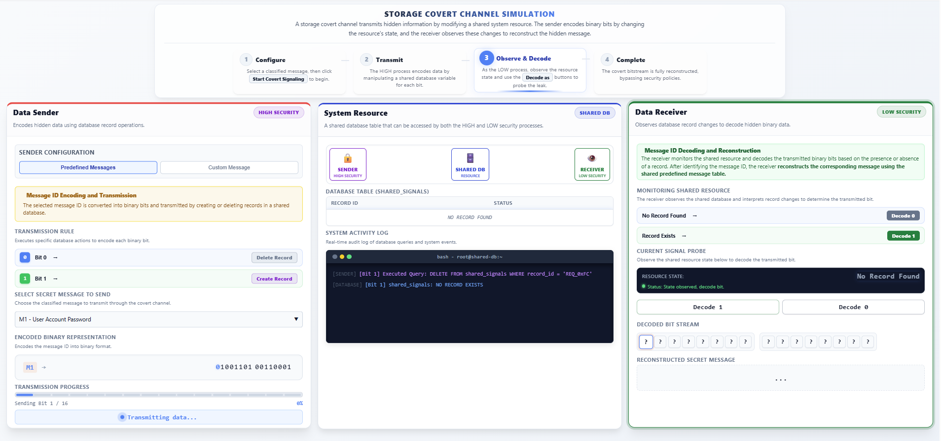
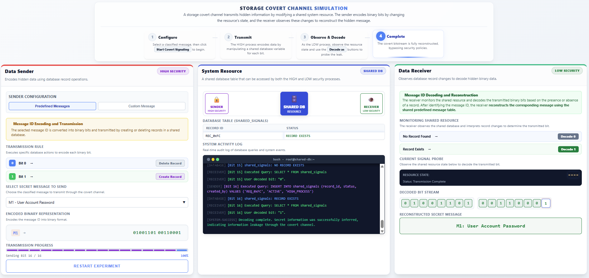
Step 3: Receiver Phase – Decode and Reconstruct Message
- In the right panel (DATA RECEIVER - LOW SECURITY):
- The receiver monitors the Resource State in the Current Signal Probe.
- Manually Decode each bit:
- Click Decode 1 if you observe the record exists in the shared table.
- Click Decode 0 if you observe the record is absent.
- Observe the Decoded Bit Stream filling up as you identify each bit.
- Verify the final Reconstructed Secret Message matches the original secret sent by the HIGH process.
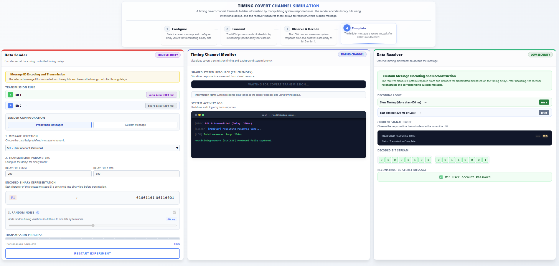
2. Timing Covert Channel
- In the top navigation bar, select the Timing Channel option.
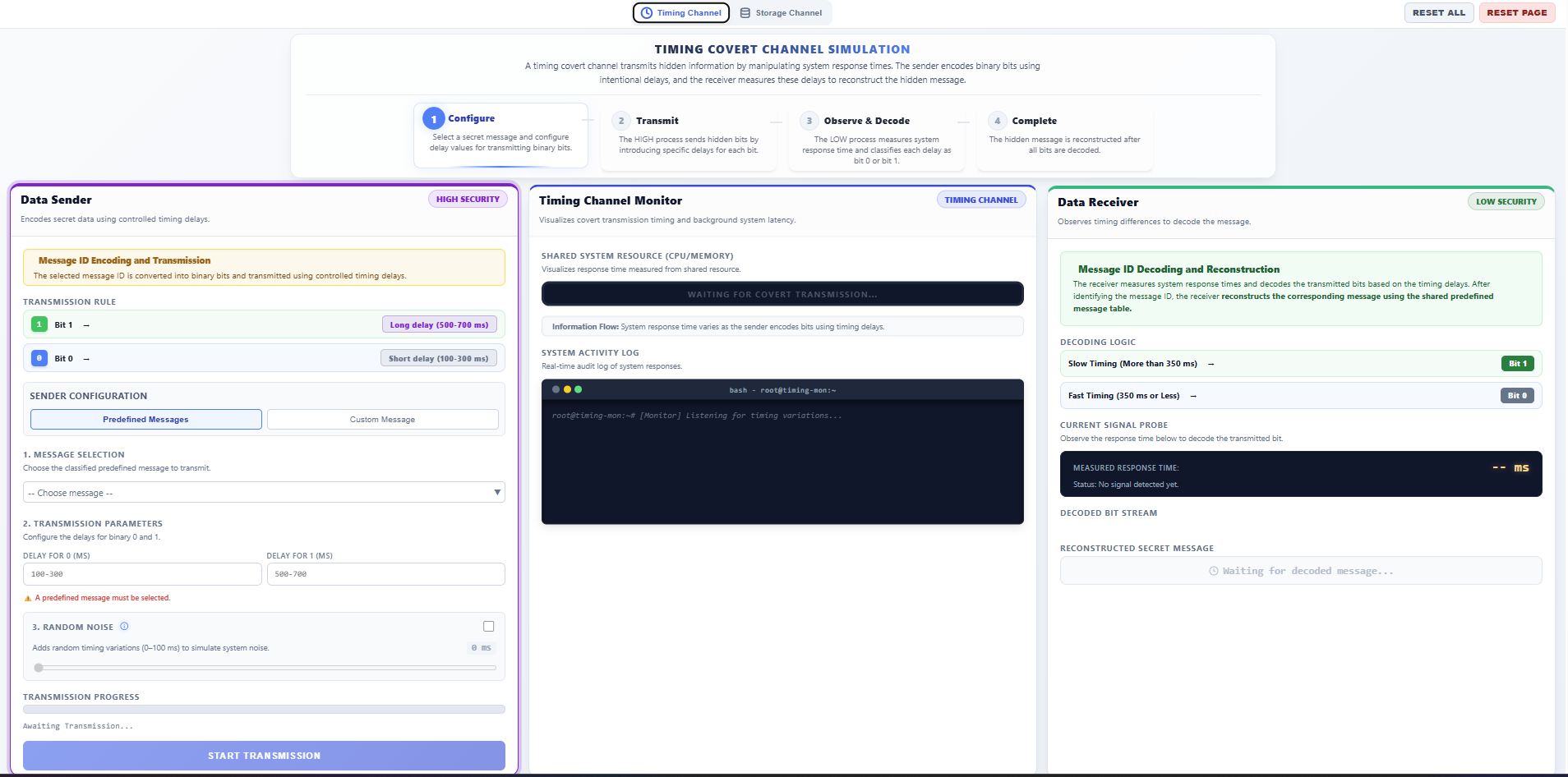
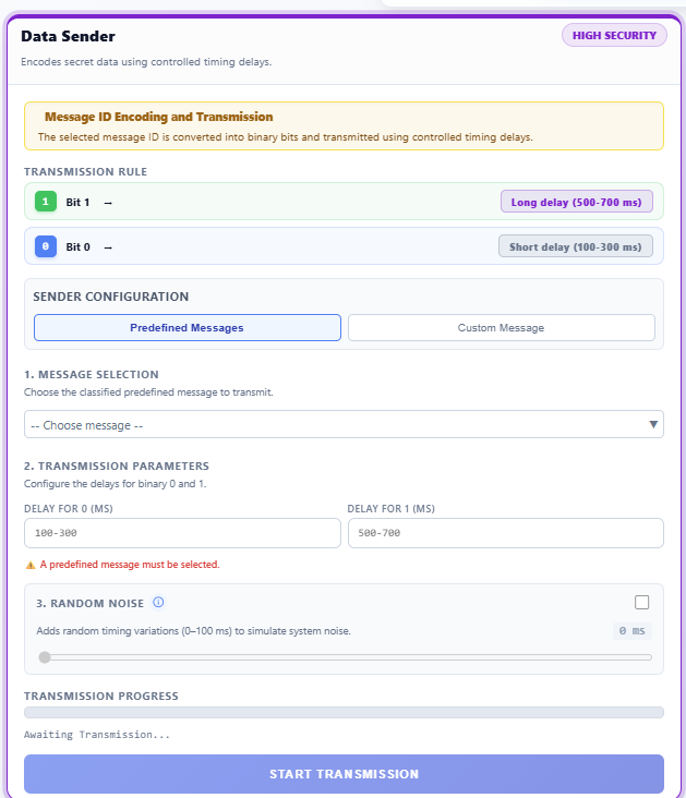
Step 1: Sender Phase – Configure Timing Parameters
- In the left panel (DATA SENDER - HIGH SECURITY):
- Message Type: Select either Predefined Messages or Custom Message.
- Configure Delays: Set the timing intervals for transmission:
- Delay for 1: Set a longer delay (e.g., 500-700ms).
- Delay for 0: Set a shorter delay (e.g., 100-300ms).
- Random Noise (Optional): Enable to simulate real-world system jitter and see how it affects decoding accuracy.
- Click START TRANSMISSION.
Step 2: Observation Phase – Observe System Latency
- In the center panel (SYSTEM MONITOR):
- Observe the Shared System Resource. The animation shows varying processing times for each request.
- Notice how the HIGH process intentionally creates measurable "waits" to signal data through CPU usage timing.
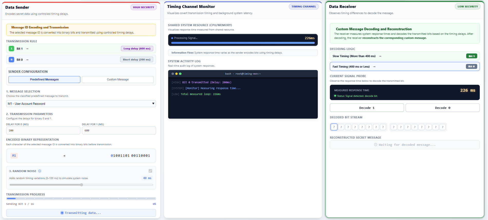
Step 3: Receiver Phase – Measure and Recover Data
- In the right panel (DATA RECEIVER - LOW SECURITY):
- Monitor the Operation Duration recorded in milliseconds.
- Deduce the Bit:
- Press Decode 1 if a long delay is measured.
- Press Decode 0 if a short delay is measured.
- Continue until the Decoded Bit Stream is complete and the Reconstructed Secret Message is displayed.