
Study of Connecting Rod in an Internal Combustion Engine
Connecting Rod
In a reciprocating piston engine, the connecting rod connects the piston to the crankshaft. It is fastened to the piston at its small end by a piston pin, also known as a gudgeon pin. Together with the crank, they form a simple mechanism that converts linear motion into rotating motion. The big end is attached to the crankshaft at the crankpin journal. A connecting rod is rigid; it may transmit either a push or a pull and hence can rotate the crank through both halves of a revolution, i.e., piston pushing and piston pulling. In a few two-stroke engines, the connecting rod is only required to push. They are cast or forged to form an H-section near the small end and an I-section near the big end. This shape provides greater strength to resist stresses than a solid rod of the same mass. To maintain engine balance, all the connecting rods in an engine are manufactured as a matched set.
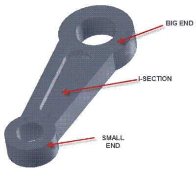
Figure: Connecting Rod
The connecting rod carries the engine motive energy directly to the crank, attaining high-level performance. Connecting rods must be light in weight and yet strong enough to transmit the thrust of the pistons to the crankshaft. They are generally drop forged from steel alloys capable of withstanding heavy loads without bending or twisting. Holes at the upper and lower ends are machined accurately to permit proper fitting of bearings, and these holes must be perfectly parallel.
Design
The H–I beam design is stronger and more durable than traditional rods. The thickness of the web at the beam is increased. It reduces the early signs of fatigue and provides a long life that can withstand stress in high-revolution engines.
Materials
Only a handful of materials are considered appropriate for the use in engine connecting rod construction. Titanium and aluminum are two popular materials used in construction of connecting rods, specifically for performance vehicles due to their light weight. Drop-forged steel alloys into connecting rods results in a connecting rod that is capable of handling heavy loads without bending, breaking, or twisting.
Cross Grain Flow
A special cross-grain flow process creates a memory action that keeps the connecting rod caps round even during extreme high-speed operation. When rods are made, they have grain patterns, like wood. The body or neck of the connecting rod is manufactured with vertical grain flow, while the caps are made with horizontal grain flow for improved strength and durability.
Facts
Connecting rods used in internal combustion engines needs to be durable but relatively lightweight. They should be capable of withstanding piston thrust and efficiently transmitting thrust to the crankshaft. Connecting rods are available in an assortment of sizes depending on engine requirements.
Connecting Rod in Internal Combustion Engines
In modern automotive internal combustion engines, the connecting rods are most usually made of steel for production engines, but can be made of T6-2024 and T651-7075 aluminum alloys (for lightness and the ability to absorb high impact at the expense of durability) or titanium (for a combination of lightness with strength, at higher cost) for high performance engines, or of cast iron for applications such as motor scooters. They are not rigidly fixed at either end, so that the angle between the connecting rod and the piston can change as the rod moves up and down and rotates around the crankshaft. Connecting rods, especially in racing engines, may be called "billet" rods, if they are machined out of a solid billet of metal, rather than being cast. The small end attaches to the piston pin, gudgeon pin or wrist pin, which is currently most often press fit into the connecting rod but can swivel in the piston, a "floating wrist pin" design. The big end connects to the bearing journal on the crank throw, in most engines running on replaceable bearing shells accessible via the connecting rod bolts which hold the bearing "cap" onto the big end. Typically there is a pinhole bored through the bearing and the big end of the connecting rod so that pressurized lubricating motor oil squirts out onto the thrust side of thecylinder wall to lubricate the travel of the pistons and piston rings. Most small two-stroke engines and some single cylinder four-stroke engines avoid the need for a pumped lubrication system by using a rolling-element bearing instead, however this requires the crankshaft to be pressed apart and then back together in order to replace a connecting rod. The connecting rod is under tremendous stress from the reciprocating load represented by the piston, actually stretching and being compressed with every rotation, and the load increases to the square of the engine speed increase. Failure of a connecting rod, usually called "throwing a rod" is one of the most common causes of catastrophic engine failure in cars, frequently putting the broken rod through the side of the crankcase and thereby rendering the engine irreparable; it can result from fatigue near a physical defect in the rod, lubrication failure in a bearing due to faulty maintenance, or from failure of the rod bolts from a defect, improper tightening. Re-use of rod bolts is a common practice as long as the bolts meet manufacturer specifications. Despite their frequent occurrence on televised competitive automobile events, such failures are quite rare on production cars during normal daily driving. This is because production auto parts have a much larger factor of safety, and often more systematic quality control.
When building a high performance engine, great attention is paid to the connecting rods, eliminating stress risers by such techniques as grinding the edges of the rod to a smooth radius,shot peening to induce compressive surface stresses (to prevent crack initiation), balancing all connecting rod/piston assemblies to the same weight and Magnafluxing to reveal otherwise invisible small cracks which would cause the rod to fail under stress. In addition, great care is taken to torque the connecting rod bolts to the exact value specified; often these bolts must be replaced rather than reused. The big end of the rod is fabricated as a unit and cut or cracked in two to establish precision fit around the big end bearing shell. Therefore, the big end "caps" are not interchangeable between connecting rods, and when rebuilding an engine, care must be taken to ensure that the caps of the different connecting rods are not mixed up. Both the connecting rod and its bearing cap are usually embossed with the corresponding position number in the engine block. Recent engines have connecting rods made using powder metallurgy, which allows more precise control of size and weight with less machining and less excess mass to be machined off for balancing. The cap is then separated from the rod by a fracturing process, which results in an uneven mating surface due to the grain of the powdered metal. This ensures that upon reassembly, the cap will be perfectly positioned with respect to the rod, compared to the minor misalignments which can occur if the mating surfaces are both flat. A major source of engine wear is the sideways force exerted on the piston through the connecting rod by the crankshaft, which typically wears the cylinder into an oval cross-section rather than circular, making it impossible for piston rings to correctly seal against the cylinder walls. Geometrically, it can be seen that longer connecting rods will reduce the amount of this sideways force, and therefore lead to longer engine life. However, for a given engine block, the sum of the length of the connecting rod plus the piston stroke is a fixed number, determined by the fixed distance between the crankshaft axis and the top of the cylinder block where the cylinder head fastens; thus, for a given cylinder block longer stroke, giving greater engine displacement and power, requires a shorter connecting rod (or a piston with smaller compression height), resulting in accelerated cylinder wear.
Compound Rods
Many-cylinder multi-bank engines such as a V12 layout have little space available for many connecting rod journals on a limited length of crankshaft. This is a difficult compromise to solve and its consequence has often led to engines being regarded as failures. The simplest solution, almost universal in road car engines, is to use simple rods where cylinders from both banks share a journal. This requires the rod bearings to be narrower, increasing bearing load and the risk of failure in a high-performance engine. This also means the opposing cylinders are not exactly in line with each other. In certain engine types, master/slave rods are used rather than the simple type. The master rod carries one or more ring pins to which are bolted the much smaller big ends of slave rods on other cylinders. Certain designs of V engines use a master/slave rod for each pair of opposite cylinders. A drawback of this is that the stroke of the subsidiary rod is slightly shorter than the master, which increases vibration in a v engine, catastrophically so for the Sunbeam Arab. Radial engines typically have a master rod for one cylinder and multiple slave rods for all the other cylinders in the same bank. The usual solution for high-performance aero-engines is a "forked" connecting rod. One rod is split in two at the big end and the other is thinned to fit into this fork. The journal is still shared between cylinders. The Rolls-Royce Merlin used this "fork-and-blade" style.