
BJT Common Emitter Characteristics 
Procedure
BJT Common Emitter - Input Characteristics
- Initially set rheostat Rh1 = 1 Ω and rheostat Rh2 = 1 Ω
- Set the Collector-Emitter Voltage(VCE) to 1 V by adjusting the rheostat Rh2
- Base Emitter Voltage(VBE) is varied by adjusting the rheostat Rh1.
- Note the reading of Base current(IB)in micro Ampere.
- Click on 'Plot' to plot the I-V characteristics of Common-Emitter configuration. A graph is drawn with VBE along X-axis and IB along Y-axis.
- Click on 'Clear' button to take another sets of readings
- Now set the Collector-Emitter Voltage(VCE) to 2 V, 3 V, 4 V
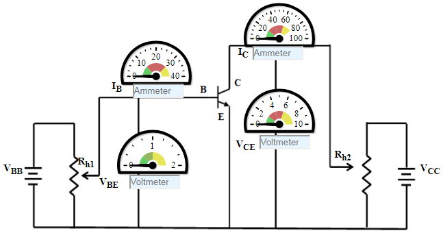
Figure:1
BJT Common Emitter - Output Characteristics
- Initially set rheostat Rh1 = 1 Ω and rheostat Rh2 = 1 Ω
- Set the Base current(IB)15 uA by adjusting the rheostat Rh1
- Vary the Collector-Emitter Voltage(VCE)is varied by adjusting the rheostat Rh2.
- Note the reading of Collector current(IC).
- Click on 'Plot' to plot the I-V characteristics of Common-Emitter configuration. A graph is drawn with VCE along X-axis and IC along Y-axis.
- Click on 'Clear' button to take another sets of readings
- Now set the Base Current(IB) to 20 uA
Figure: 2