
Characteristics of Zener diode
Procedure
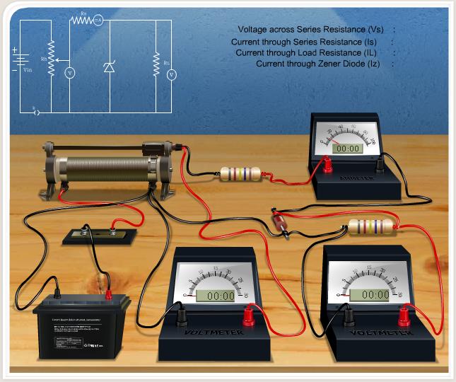
Apparatus:
Diode, resistor, variable DC power supply, milliammeter, voltmeter, Rheostat and wire.
Controls
- Insert Key Button: This is used to insert the key on the switch connected with the battery. This key is only activated when the connection is perfect.
- Choose Zener Diode: This combo box is used to select different Zener diodes having different Zener voltages.
- Series Resistance: The value of the series resistance can be directly input here.
Slider
- Rheostat Value: The rheostat can be controlled by using this slider.
- Load Resistance: The value of the load resistance can be set or changed using this slider.
Button
- Reset Button: Used to reset all the connections.
Procedure
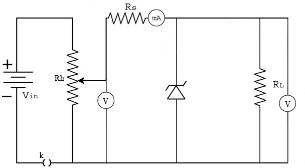
Using the circuit diagram, identify the connections in the given platform. Connections are made as shown in the diagram below.
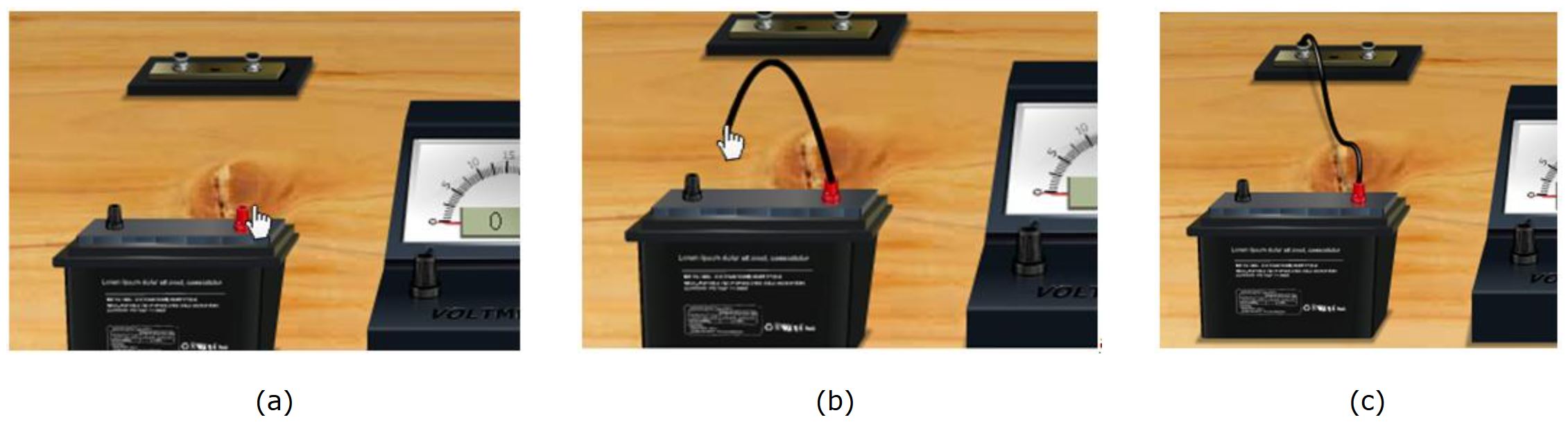
How to make connections in simulation ?
Click one end node of the battery and drag to the next position, where we want to connect the wire. Just like shown in the figures below:
Connection diagram
- If the connections are correct, the Insert Key option is activated.
Slowly increase the reverse voltage in small increments.
Record the voltage across the Zener diode and the corresponding current.
Continue increasing the reverse voltage until the Zener breakdown voltage is reached. Beyond this point, observe that the voltage across the diode remains nearly constant while the current increases rapidly.
Note: This is an ideal circuit. For a real circuit, there will be small variations in output voltage with varying input voltage or load resistance.