Characteristics and parameters of Op-Amp
A. Measurement of Input Bias Current IB
Familiarise with components

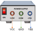


Fig 1: Components
a) Measurement of inverting bias current IB1
1. Click on the components button to place the component on the table.
2. Make connections as per the circuit diagram or connection table.
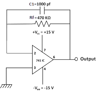
Fig 2: Circuit diagram to measure inverting bias current.
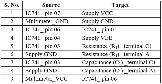
Table 1: Connection table to measure inverting bias current.
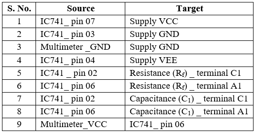
3. Click on 'Check Connection' button to check connections. If correct, Click on 'Show output voltage' button to view output on DMM.
4. Calculate the inverting bias current using the formula:
IB1 = Vo/Rf
5. Click on 'Result' button and enter the calculated value.
6. Click on 'Reset' button and proceed in the same way to calculate the input bias current at non-inverting terminal.
b) Measurement of non-inverting bias current IB2
1. Click on the components button to place the component on the table.
2. Make connections as per the circuit diagram or connection table.
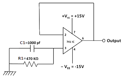
Fig 3: Circuit diagram to measure non-inverting bias current.
Table 2: Connection table to measure non-inverting bias current.
3. Click on 'Check Connection' button to check connections. If correct, Click on 'Show output voltage' button to view output on DMM.
4. Calculate the non-inverting bias current using the formula:
IB2 = Vo/R1
5. Click on 'Result' button and enter the calculated value.
6. The input bias current IB hence, can be calculated using the formula:
IB = (IB1 + IB2)/2
where, IB1 has to be calculated from previous part.
B. Measurement of input offset current Iio
1. Click on the components button to place the component on the table.
2. Make connections as per the circuit diagram or connection table.
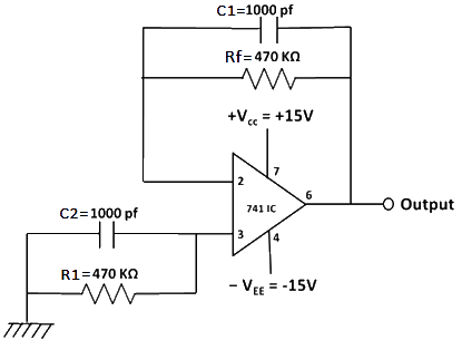
Fig 4: Circuit diagram to measure input offset current.
Table 3: Connection table to measure input offset current.
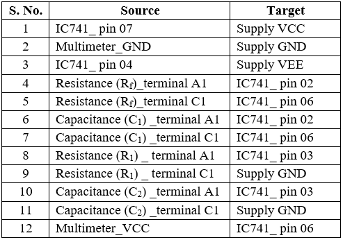
3. Click on 'Check Connection' button to check connections. If correct, Click on 'Show output voltage' button to view output on DMM.
4. Calculate the input offset current using the formula:
Iio = Vo/Rf
5. Click on 'Result' button and enter the calculated value.
C. Measurement of input offset voltage Vio
1. Click on the components button to place the component on the table.


Fig 5: Components
2. Make connections as per the circuit diagram or connection table.
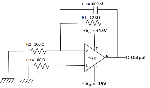
Fig 6: Circuit diagram to measure input offset voltage.
Table 4: Connection table to measure input offset voltage.
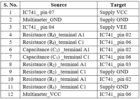
3. Click on 'Check Connection' button to check connections. If correct, Click on 'Show output voltage' button to view output (Vo) on DMM.
4. Calculate the input offset voltage, Vio using the formula:
Vio = (Vo - IioRf)/(1+Rf/Ri)
5. Click on 'Result' button and enter the claculated value.
D. Measurement of slew rate S.R.
1. Click on the components button to place the component on the table.


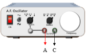

Fig 7: Components
2. Make connections as per the circuit diagram or connection table.
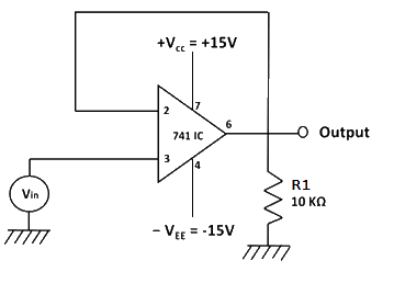
Fig 8: Circuit diagram to measure slew rate.
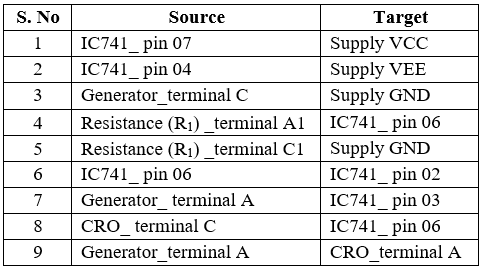
Table 5: Connection table to measure slew rate.
3. The input signal* has to be taken from the red terminal of A.F. Oscillator while the other terminal has to be grounded.
4. Also, feed the input signal to channel CH1 of the C.R.O and the output from Op-Amp IC must be fed to the channel CH2.
5. Click on 'Check Connection' button to check connections. If correct, Click on 'Show output voltage' button to view output.
6. Increase the frequency of input signal using the dial** on A.F. Oscillator until output wave becomes triangular. This is the required frequency fmax in KHz.
7. Calculate the slew rate using the formula:
S.R. = 2πfmaxVm/106 V/μs
*Amplitude of input signal 'Vm' is 3V.
** dial can be controlled through both mouse and keyboard.
