Bistable Multivibrator using 555-Timer IC.
1. Fill the truth table and click on Check button.
2. Click on the components button to place the component on the table.


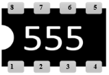
Fig. 1: Components
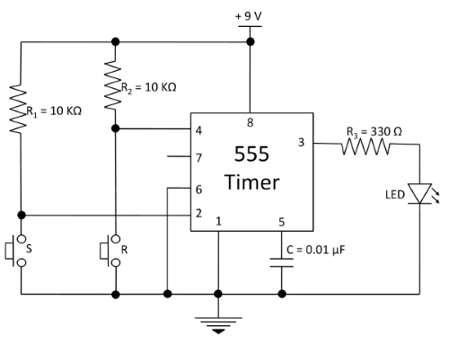
3. Make connections as per the circuit diagram or connection table.

Fig. 2: Circuit diagram of bistable multivibrator.
Table 1: Connection table of bistable multivibrator

4. Once the connections are made, click on 'Check Connections' button. If connections are right, the 'Start Simulation' button will become active. Click on it to start the simulation.
5. Click on 'Set' and 'Reset' tactile buttons to provide inputs to the circuit.
