Behaviour of an RC Beam in Flexure
Background:
Reinforced concrete (RC) beams are structural elements that carry transverse external loads. The loads cause bending moments, shear forces, and sometimes torsion across their length. Moreover, concrete is strong in compression and very weak in tension. Thus, steel reinforcement is used to take up tensile stresses in RC beams.
Beams are divided into two categories based on the presence of tension and compression steel -
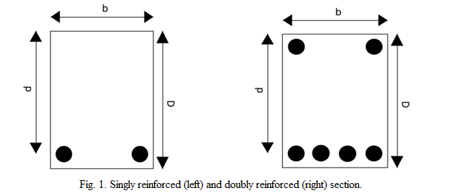
- Singly Reinforced Beam ( see Fig. 1 (A) )
A beam section with steel only on the tension side is a singly reinforced beam. - Doubly Reinforced Beam ( see Fig. 1 (B) ) A beam section with steel on the tension and compression side is known as a doubly reinforced beam.
- Balanced Section: The area of tension steel is such that the two limiting conditions (yielding of steel and crushing of concrete) are reached simultaneously.
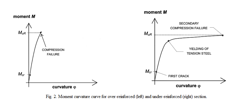
- Under Reinforced (UR) Section: The area of tension steel is such that the beam fails by yielding of tension steel followed by crushing of concrete.
- Over Reinforced (OR) Section: The area of tension steel is such that the beam fails due to the crushing of concrete.
As per the limit state design method given in IS-456, the design ultimate moment of resistance of an UR section is given by:
Mur,design = 0.36fckbxu(d-0.416xu)
where
xu = (0.87fyAst) / (0.362fckb) < xu,max
and where
xu,max / d = 0.0035 / ( 0.0055 + 0.87fy/Es )
The predicted ultimate moment of resistance of a UR section is given by setting the values of factors of safety for both concrete and steel equal to 1.0 and by considering the observed (mean) strength of concrete and steel instead of the characteristic values. With this, the predicted ultimate moment of resistance of an UR section is given by:
Mur,predicted = 0.54fcmbxu(d-0.416xu)
where
xu = (fy,mAst) / (0.54fcmb) < xu,max,predicted
and where
xu,max,predicted / d = 0.0035 / ( 0.0055 + fym/Es )
In the above equation:
b = width of the beam
D = depth of the beam
d = effective depth of the beam
Ast = area of steel in tension
fym = mean yield strength of steel
fy = characteristic yield strength of steel
fcm = mean compressive strength of concrete
fck = characteristic compressive strength of concrete
Es = elastic modulus of steel (= 200 GPa)
xu = depth of neutral axis
xu,max = limiting depth of neutral axis
Mur,design = design ultimate moment of resistance
Mur,predicted = predicted ultimate moment of resistance
Mur,observed = observed (experimental) ultimate moment of resistance
Test setup:
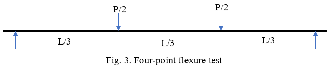
A combination of tensile, compressive, and shear stresses usually determines the strength of the concrete beam when it is subjected to flexure or bending loads. In this test, a four-point (also called third point) loading setup is selected to study the flexural behavior of the concrete beam, as shown in the Fig. 3.
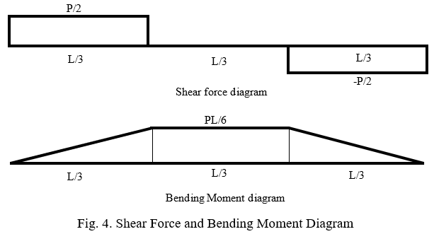
The middle portion of the beam is subjected to pure flexure as sheer stress in this region is zero. The bending moment and shear force diagram are shown in the following Fig. 4.