
Application of basic logic gates in fire and burglar alarms.
Procedure
A. Procedure for Fire Alarm Simulation
1. Fill the truth table and click on check button.
2. Click on the component button to place the component on the table.


")
")


Fig. 1: Components
3. Make connections as per the circuit diagram and pic diagrams of ICs or connection table.
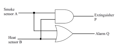
Fig. 2: Circuit diagram of fire alarm using logic gate ICs.

Fig. 3: Pin diagram of IC-7408.
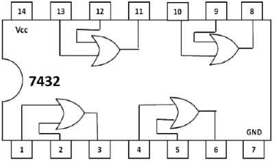
Fig. 4: Pin diagram of IC-7432.
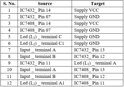
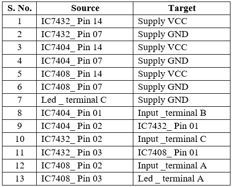
Table 1: Connection table for fire alarm simulation.
4. Click on 'Check Connections' button. If connections are right, the 'Start Simulation' button will become active. Click on it to start simulation.
5. Click on the toggle switches 'A' and 'B' to perform simulation.
B. Procedure for Burglar Alarm Simulation
1. Fill the truth table and click on check button.
2. Click on the component button to place the component on the table.
3. Make connections as per the circuit diagram and pin diagram of the ICs or connection table.
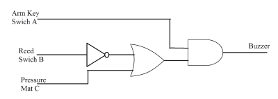
Fig. 5: Circuit diagram of burglar alarm using logic gate ICs.
Fig. 6: Pin diagram of IC-7408.
Fig. 7: Pin diagram of IC-7432.
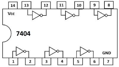
Fig. 8: Pin diagram of IC-7404.
Table 2: Connection table for burglar alarm simulation.
4. Click on 'Check Connections' button. If connections are right, the 'Start Simulation' button will become active. Click on it to start simulation.
5. Click on the toggle switches 'A', 'B' and 'C' to perform simulation.