
Receiver Architecture : ZF, MMSE
Imagine transmitting a signal over an additive white Gaussian noise (AWGN) channel. Here, the channel only adds noise, without distorting the signal’s amplitude or phase. The received signal here is . As a result, detection is relatively straightforward. The receiver’s task is simply to handle the noise during detection.
However, in wireless channels, signals do not just see noise but they pass through a fading channel resulting in the received signal . The channel response is generally complex and thus induces magnitude and phase shifts. Due to this, the constellation points will be shifted and rotated. These distortions must be compensated before decoding. Thus, we need to remove the effect of before decoding. To facilitate this, the receiver employs channel equalizers, which act like inverse filters that attempt to cancel out the channel’s effects.
In a narrowband fading channel, the bandwidth of the transmitted signal is small compared to the channel’s coherence bandwidth. This means the channel appears as a single complex gain across the entire signal (i.e. flat fading) — effectively, the same attenuation and phase shift is applied to all frequencies. Equalization in this case is relatively straightforward, since the receiver only needs to invert to restore both the amplitude and phase of the transmitted signal.
In contrast, in wideband wireless communication, a fundamental challenge is frequency-selective fading, which occurs when delay spread of the wireless channel is significantly larger compared to the symbol duration. Because wideband signals occupy a large bandwidth, their symbol duration is short. When the delay spread of the multipath components is larger than the symbol duration, adjacent symbols tend to overlap in the superposition of the received multiple delayed copies of the signal. This phenomenon is called Inter-Symbol Interference (ISI). From a frequency-domain perspective, the received signal can be expressed as , where varies with frequency. Thus, the distortion is not only in amplitude and phase but is also frequency-selective, meaning different parts of the signal spectrum are affected differently. ISI severely degrades system performance because symbols interfere with one another, making reliable detection difficult. To address ISI in frequency-selective fading channels, several techniques are commonly employed, including:
- Channel Equalization - The equalizers are used on the reciever side to reverse the effects of the channel and recover the transmitted signal.
- Multi-Carrier Modulation - Splitting the wideband channel into multiple narrowband subcarriers.
- Spread Spectrum - Spreading the signal over a wide frequency band to reduce the impact of fading on any particular frequency component.
In this experiment, we study channel equalization in narrowband fading scenario. The following diagram shows equalizer equipped MIMO systems.
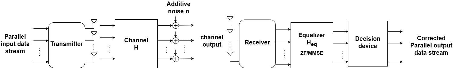
The signal arriving at the reciever can be modeled as
where is the transmitted symbol vector and is the awgn noise.
This experiment focuses on channel equalization i.e removing the effect on on the received signal so that it becomes decodable. To do this, we will now describe the two popular equalization techniques:
- Zero Forcing (ZF) equalizer and
- Minimum Mean Square Error (MMSE) equalizer.
These methods are implemented to mitigate the channel impact, and each has distinct characteristics in terms of handling noise and channel response.
ZF Equalizer
ZF equalizer is a fundamental technique designed to completely reverse the impact of the channel on the received signal. It achieves this by applying a filter that is the inverse of the channel’s frequency response. Mathematically, the ZF equalizer is defined by a filter
The received signal after ZF equalization reduces to
The ZF equalizer restores the transmitted signal by "forcing" the effect of the channel to zero on desired component. However, we can observe from the above equation that this approach has a significant drawback: when the channel gain is small or near zero, the ZF equalizer amplifies the noise component in the received signal. This issue is particularly problematic in low Signal-to-Noise Ratio (SNR) regimes. Thus ZF equalizer usually has poor bit error rate (BER) performance in low SNR regimes. To combat for this, we move to understand MMSE equalizer.
MMSE Equalizer
MMSE equalizer is designed to optimize signal recovery by balancing the trade-off between channel inversion and noise amplification. Unlike the ZF equalizer, the MMSE equalizer does not completely negate the channel's impact; instead, it minimizes the mean square error between the transmitted symbol vector and the estimated symbol vector .
Mathematically, this optimization problem is formulated as:
Solving this optimization problem yields the linear MMSE filter, given by
where is the noise variance.
The received signal after MMSE equalization reduces to
The MMSE equalizer provides a better balance between channel inversion and noise amplification by scaling the received signal with . Because of this scaling, the SNR of the equalized and originally received signal remain unchanged. However, it is interesting to note that when the channel is poor (i.e., ), the term will restrict the noise amplification. On the contrary, when the channel is good (i.e., ), the MMSE equalizer reduces to the ZF equalizer. Thus, we observe that MMSE provides additional benefits in the low SNR regime while performing on par with ZF under good channel conditions.
Comparative Performance of ZF and MMSE Equalizers
In this experiment, we will compare the ZF and MMSE equalizers by implementing them and observing their performance across different SNR conditions. The ZF equalizer will illustrate the effect of noise amplification, particularly in low SNR, while the MMSE equalizer will demonstrate better BER performance by minimizing the impact of noise. Through this comparison, the experiment aims to highlight the trade-offs involved in selecting equalization techniques for wireless communication systems.