
Anderson's Bridge
Procedure
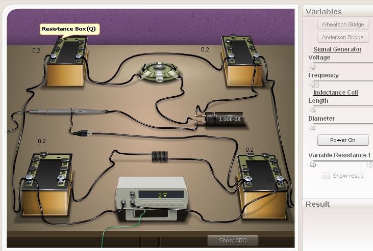
Slider Region
Signal generator
- Voltage- This slider is used to vary the voltage of the signal generator.
- Frequency- Using this slider we can fix the frequency for a particular voltage.
Inductance coil:
- Length- This slider is used to change the length of the inductance coil used in the circuit. There are 1000 number of turns in 1m length of the coil.
- Diameter- This slider help us to fix the diameter of the core material of the coil.
Power On Button- This button enables the user to start the experiment after the connnections are made. It will be active only when the whole connections done properly.
Variable Resistance r - This slider is used to balance the circuit after fixing the suitable resistances in the P, Q, R and S resistance boxes.
Resistance Boxes - The value of the resistances in P, Q, R and S can be varied from fractional to small by clicking and removing the tick mark in the pop up box.
Capacitor - Here 0.01μF capacitor is used.
Connection Diagram
Wheatstone's bridge
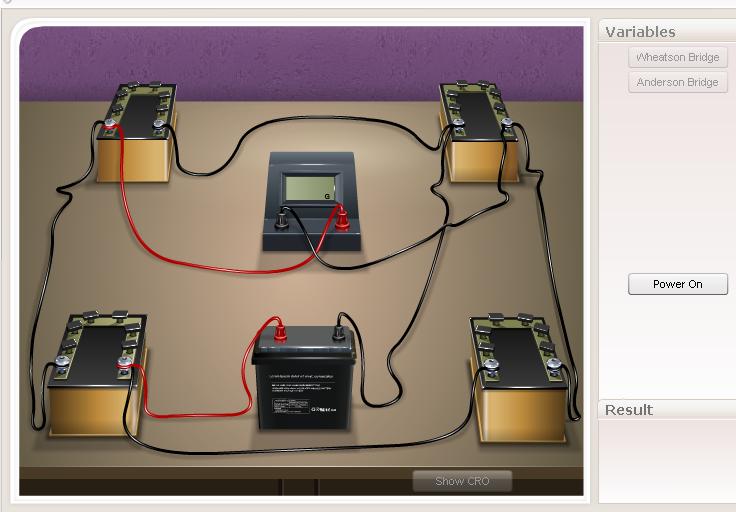
Connections can make using connection wire by click and drag option.
Anderson's Bridge
Procedure for doing simulator
- Connections are made using the above connection diagram for wheatsons bridge and Anderson's bridge .
- Power on the switch of siganal generator.
- Apply pariticular Voltage and frequency.
- Select particular length for inductance coil and diameter for core.
- Give a particular resistance value for P resistance box and other value of resistances in Q, R and S will automatically appear.
- The value of variable resistor 'r' can be varied either by using the slider or by clicking the arrow displayed in the resistor.
- Note the value of r, where the voltage in CRO becomes zero is the balancing condition.
Note: The value of resistances in the four resistance boxes are suitable to attain balancing condition, the variable resistor, r will automatically display a value near the balancing condition. Otherwise variable resistor displays the minimum value of 1Ω. 8. The experiment is repeated by using " reset" button. Also we can hold the connections and can change the parameters by " Power off " button.
Procedure for real lab
Connections are made as shown in the theory. A.C. source say a 1000Hz audio-oscilloscope and a head set is used here. Keeping the value of P, Q, R and S constant, adjust the value of variable resistance r till the sound is reduced to a minimum value. This is the balancing point of the alternating current. Note the value of resistance r and capacitor C. Repeat the experiment three times and calculate the self inductance of the coil using equations.
Observations and Calculations
Where C = 0.01μF
Where f is the frequency and L is the self inductance of the coil.
Results
- The self inductance (L) of a coil using Anderson's Bridge =.............. H
- The inductive reactance( XL) of the coil at a particular frequency of the given coil =......... Ω