Measurement of Self Inductance accurately by Anderson's Bridge 
Theory
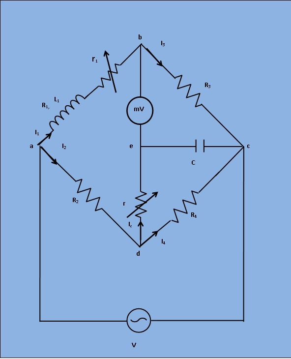
This bridge is a modification of the maxwell's inductive and capacitive bridge. In this method, the self inductance is measured in terms of a standard capacitor. This method is applicable for precise measurement of self inductance over wide range of values. Figure 1 shows the circuit diagram of the bridge for balance conditions.

Fig 1: Circuit diagram for Measurement of Self Inductance by Anderson's Bridge
Let,L1=Self inductance is to be measured.
R1= Resistance of self inductor.
r1= Resistance connected in series with self inductor.
r,R2,R3,R4= Known non inductive resistances.
C = Fixed standard capacitor.
At balance,
I1= I3 and I2=IC+I4
now,
$$ I_1R_3 =I_C/(j \omega C) \ then I_C=I_1 j \omega CR_3...(1) $$
Writing the other balance equations,
$$ I_1(r_1+R_1+j \omega L_1) = I_2R_2+rI_C...(2) $$
$$ I_C(r+\frac{1}{j \omega C}) = (I_2-I_C)R_4 $$
Substituting the value of IC in equation (2) , we get
$$ I_1(r_1+R_1+j \omega L_1) = I_2R_2+I_1 j \omega CrR_3 $$
or,$$ I_1(r_1+R_1+j \omega L_1-j \omega CrR_3) = I_2R_2...(3) $$
and
$$ j \omega CR_3I_1(r+\frac{1}{j \omega C}) = (I_2-I_1j \omega CR_3)R_4 $$
or,$$ I_1(j \omega CrR_3+j \omega CR_3R_4) = I_2R_4...(4) $$
From equations (3) and (4) , we get by equating real and imaginary parts,
$$ R_1 = \frac{R_2R_3}{R_4-r_1}...(5) $$
$$ L_1 = C \frac{R_3}{R_4}[r(R_4+R_2)+R_2R_4]...(6) $$
An examination of balance equation reveals that to obtain easy convergence of balance , alternate adjustments of r1 and r should be done as they appear in only equ. (1) and (2).