Determination of the Incremental Transfer Function of an AC Servomotor 
Theory
Servomotors
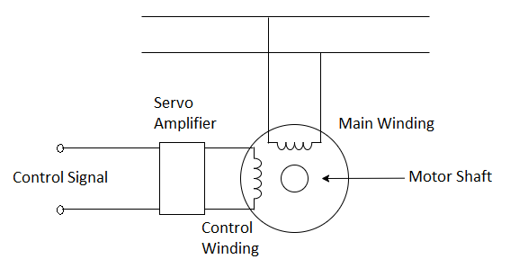
Servomotors (control motors) are the motors, designed and built for the use in feedback control systems.
They have high speed of response and they are made for dc as well as for ac operation. These motors are usually fractional horsepower motors having low efficiency.

Fig. 1. Schematic representation of a Servomotor
The two phase induction motor is used as a servomotor. This is because
No brushes and slip-rings are used. Thus, less maintenance is required and the motor is rugged and robust in construction.
The motor requires only a simple control amplifier.
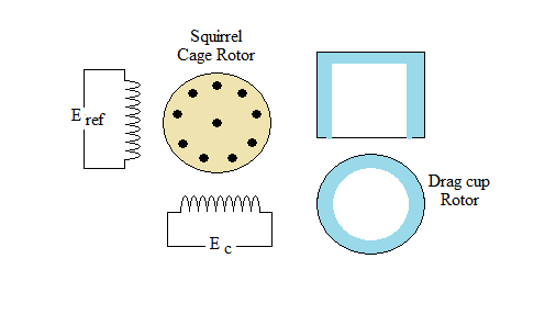
A schematic of the two-phase induction motor is shown in Fig. 2. The motor consists of a stator with two distributed windings displaced by 90 electrical degrees apart. Under normal operating conditions in control applications, a fixed voltage from a constant voltage source is applied to one phase called the fixed or the reference phase (Eref). The other phase is called the control phase, energized by a voltage (Ec) which is 90 degrees out of phase with respect to the voltage of the reference phase. The control phase voltage is usually supplied from a servo amplifier, the voltage has a variable amplitude and polarity. The direction of rotation of the motor reverses when the control phase signal Changes its sign. The rotor is squirrel cage or drag-cup type in structure.

Fig. 2. Schematic of a Two-Phase Induction Motor
Unlike a dc motor the torque-speed curve of a two phase induction motor is quite nonlinear. Considering Fig. 3, as the reference phase voltage is kept fixed, the motor torque Tm is a function of the speed and the control phase voltage and is represented by,
$$T_m = f ( \dot{\theta} , E ) \tag 1$$
$$where, \ \dot{\theta} = \ speed , \ E = \ control \ phase \ voltage$$

Fig. 3. Speed-Torque characteristics of an ac Servomotor
$$Let \ us \ choose \ (E_0,\dot{\theta}_0) \ be \ the \ operating \ point \ of \ the \ ac \ servomotor$$
Expanding equation (1) about the operating point with Taylor series expansion we have,
$$T_m = T_{m0} + \frac{\partial T_m}{\partial E}\vert \dot{\theta_0}E_0 (E - E_0) + \frac{\partial T_m}{\partial \dot{\theta}}\vert \dot{\theta_0}E_0 (\dot{\theta} - \dot{\theta_0}) \tag{2}$$
where the higher order terms in the Taylor series expansion are neglected.
Let
J = Moment of inertia of rotor and disc
f = Coefficient of viscous friction
TL = Load torque
$$K = \frac{\partial T_m}{\partial E}\vert \dot{\theta_0} E_0 \dot{\theta}$$
$$f_0 = \frac{\partial T_m}{\partial \dot{\theta}}\vert \dot{\theta_0}E_0$$
Then we can write the following equations
$$T_{m0} = J \ddot{\theta_0} + f \dot{\theta_0} + T_L \tag{3}$$
$$T_m = J(\ddot{\theta_0} + \Delta \ddot{\theta_0}) + f(\dot{\theta_0} + \Delta \dot{\theta_0}) T_L \tag{4}$$
In view of (2)–(4), the torque equation in incremental notation can be written as:
$$ \Delta{T_{m}} =J\Delta{\ddot{\theta}}+ f\Delta{\dot{\theta}}=K\Delta{E}-f_{0}\Delta{\dot{\theta}} \tag 5$$
Hence, the incremental motor transfer function is:
$$ G_{m}(s)=\frac{\theta(s)}{E(s)}=\frac{K}{S[Js+(f+f_{0})]} \tag 6$$
$$ =\frac{K_{m}}{s(\tau_{m}s+1)} \tag 7$$
$$where, \ \ K_{m}=\frac{K}{f+f_{0}}, \tau_{m}= \frac{J}{f+f_{0}} \tag 8$$
Km = DC gain of the system, τm = Motor Time Constant
$$K = \frac{Change \ in \ torque \ in \ N-m}{Change \ in \ control \ phase \ voltage \ E \ ( \ volt \ )} \ at \ constant \ speed \ in \ rad/sec$$
$$f_0 = \frac{Change \ in \ torque \ in \ N-m}{Change \ in \ speed \ ( \ rad/sec \ )} \ at \ constant \ control \ phase \ voltage \ E \ ( \ volt \ )$$
For linear analysis the torque – speed curves of a two phase induction motor are approximated by straight lines, as shown in Fig. 4.

Fig. 4. Linear analysis of the torque – speed curves of a two phase induction motor
Calculation for Km and τm from graph

Fig. 5. Calculation for Km and τm
Choose an operating point from the torque vs. speed graph, obtained from experiment. Let us consider operating point as (A gm-cm, B rad/sec) in fig 5 for control phase voltage 180 V. C is the torque at constant speed B rad/sec for control voltage of 200 V.
so,
$$K = \frac{(C - A) \times (9.81 \times 10^{-5})}{(200 - 180)} \ N-m \ / \ volt \tag 9$$
Now consider a slope AD for constant control phase voltage 180 V.
Where D = torque (gm-cm) for speed S rad/sec. Hence,
$$-f_0 = \frac{(D - A)\times (9.81 \times 10^-5)}{(S - B)} \ N-m \ / \ rad/sec \tag {10}$$
f0 is positive for a negative slope but it is negative for a positive slope.
Calculate the value of K and f0 from graph.
