
Analog amplitude, frequency and phase modulation and demodulation with spectrum analysis
Phase Modulation (PM)
Theory :
Phase modulation (PM) is a technique in which the phase of a carrier wave is varied according to the instantaneous amplitude of the modulating signal \( m(t) \). Unlike frequency modulation, where the carrier frequency changes, in PM the carrier amplitude remains constant while its phase is shifted. The PM signal can be mathematically expressed as:
\( S(t) = A_c \cos\left[ 2\pi f_c t + K_p m(t) \right] \)
Where:
- \( A_c \) = amplitude of the carrier signal.
- \( f_c \) = carrier frequency.
- \( K_p \) = phase sensitivity of the modulator, determining the phase shift in response to \( m(t) \).
- \( m(t) \) = message (modulating) signal.
In PM, the carrier phase \( \cos(2\pi f_c t) \) is shifted by an amount proportional to the modulating signal \( m(t) \) scaled by \( K_p \). The phase deviation is directly proportional to the amplitude of the modulating signal.
Block Diagram:
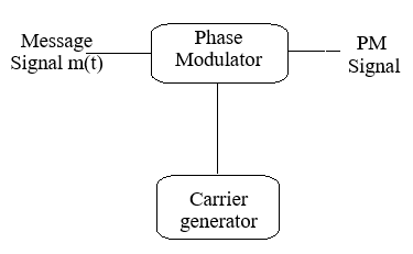
Fig 1: Phase Modulation
Modulation Index (Δφ) in Phase Modulation
In PM, the modulation index, denoted Δφ (or sometimes mp), represents the maximum phase deviation of the carrier wave in response to the modulating signal.
It is defined as:
Δφ = Kp Am
where:
- Δφ = peak phase deviation in radians.
- Am = peak amplitude of the modulating signal \( m(t) \).
- Kp = phase sensitivity of the modulator (radians per volt).
The modulation index determines the PM signal type:
- Δφ << 1 (typically Δφ < 0.3): Narrowband PM (NBPM), similar to AM.
- Δφ ≥ 1: Wideband PM (WBPM), which offers better noise immunity.
Frequency Domain Description:
A PM signal modulated by a sinusoidal tone produces an infinite number of sidebands spaced at integer multiples of the modulating frequency \( \omega_m \) around the carrier frequency \( \omega_c \).
Where:
- Jn(Δφ): Bessel function of the first kind, order n, with argument Δφ. Determines the amplitude of the nth sideband pair.
- δ(·): Dirac delta function representing discrete spectral lines.
- ωc: Carrier angular frequency (rad/s).
- ωm: Message angular frequency (rad/s).
- n: Integer (..., -2, -1, 0, 1, 2, ...) indicating sideband order.
Sidebands occur at frequencies \( \omega_c ± n \omega_m \). The spectrum is similar to FM, but in PM the modulation index Δφ is directly proportional to the modulating signal amplitude.
Phase Demodulation
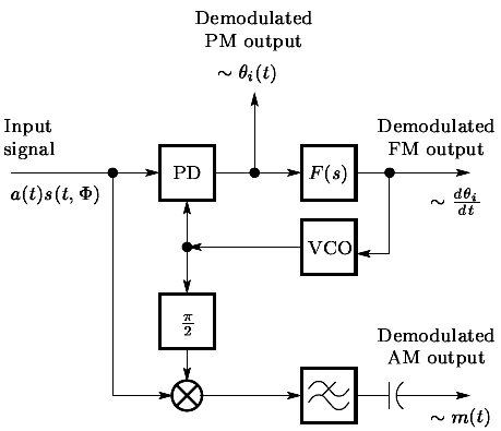
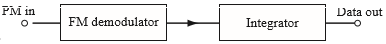
Fig 2: Phase Demodulation
Phase demodulation can be implemented using a circuit similar to an FM demodulator followed by an integrator. In PM, the message signal is encoded in the carrier’s phase. The FM demodulator converts phase variations into frequency variations, and the integrator recovers the original message signal.
- Input Signal: The input to the demodulator is the PM signal \( a(t) s(t, \Phi) \), where the phase encodes the message.
- Phase Detector (PD): Compares the incoming PM signal with the local oscillator (VCO) output and produces an error voltage proportional to the instantaneous phase difference. This output contains information about the derivative of the phase.
- FM Demodulator / Derivative Stage (F(s)): The output of the PD is passed through a frequency-demodulation block, effectively producing the time derivative of the phase: \( \frac{d\theta_i(t)}{dt} \). This represents a frequency-like signal proportional to the original message derivative.
- Integrator: Since PM encodes information in phase, integrating the derivative recovers the original message signal: \( m(t) \sim \theta_i(t) \).
- Voltage-Controlled Oscillator (VCO) and Feedback: The VCO generates a reference carrier for the PD. Feedback ensures that the PD continuously tracks the incoming PM signal for accurate demodulation.
The Final Output: After the integrator, the recovered signal is a faithful representation of the original modulating message \( m(t) \). This method effectively converts the PM demodulation problem into an FM demodulation plus integration operation.