
Analog amplitude, frequency and phase modulation and demodulation with spectrum analysis
Frequency Modulation (FM)
Theory :
Frequency modulation (FM) is the process where the frequency of a carrier wave, denoted as \( c(t) = \cos(2\pi f_c t) \), is varied in accordance with the instantaneous amplitude of the modulating signal \( m(t) \). Unlike amplitude modulation, where the amplitude of the carrier wave is varied, in FM, the amplitude remains constant while the frequency changes. The modulated signal can be mathematically expressed as:
\( S(t) = A_c \cos\left[ 2\pi f_c t + 2\pi K_f \int m(\tau) d\tau \right] \)
Where:
- \( A_c \) is the amplitude of the carrier signal.
- \( f_c \) is the carrier frequency.
- \( K_f \) is the frequency sensitivity of the modulator, defining how much the frequency of the carrier varies with the modulating signal.
- \( m(t) \) is the modulating signal.
- \( \int m(\tau) d\tau \) represents the integral of the modulating signal, which determines the frequency deviation.
This expression shows that the instantaneous frequency of the carrier wave is proportional to the amplitude of the modulating signal. The carrier frequency \( f_c \) is shifted by an amount proportional to the modulating signal \( m(t) \), resulting in a frequency-modulated signal.
Block Diagram
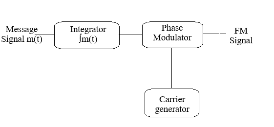
Fig 1: Frequency Modulation
Modulation Index (β) in Frequency Modulation
In FM, the modulation index, denoted by \( \beta \), represents the ratio of the peak frequency deviation to the frequency of the modulating signal:
\( \beta = \frac{\Delta f}{f_m} \)
- Δf = peak frequency deviation = \( K_f A_m \)
- f_m = maximum frequency of the message signal \( m(t) \)
- K_f = frequency sensitivity of the modulator (Hz/V)
- A_m = peak amplitude of the message signal
The value of \( \beta \) distinguishes between:
- β << 1 (typically β < 0.3): Narrowband FM (NBFM), similar to AM in properties.
- β > 1: Wideband FM (WBFM), used for high-fidelity audio with better noise immunity.
Frequency Domain Description:
An FM signal produces an infinite number of sidebands spaced at intervals of \( \omega_m \) from the carrier \( \omega_c \), both above and below.
\( S(j\omega) = \sum_{n=-\infty}^{\infty} J_n(\beta) \cdot \delta(\omega - \omega_c - n \omega_m) \)
Where:
- J_n(β): Bessel function of the first kind of order n
- δ(·): Dirac delta (impulse) at each spectral line
- ω_c: Carrier angular frequency (rad/s)
- ω_m: Message angular frequency (rad/s)
Bandwidth of an FM Signal
The bandwidth depends on the peak frequency deviation and the highest frequency in the message signal. Using Carson’s Rule, the approximate bandwidth is:
BW ≈ 2 (Δf + f_m)
- Δf = peak frequency deviation = K_f A_m
- f_m = maximum frequency of the message signal
For narrowband FM (β << 1), BW ≈ 2 f_m, similar to AM. Wideband FM (β > 1) requires more bandwidth to accommodate multiple sidebands.
Frequency Demodulation
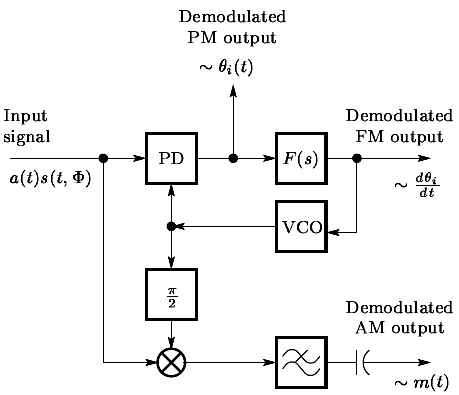
Fig 2: Frequency Demodulation using a PLL
The diagram illustrates the demodulation of an FM signal using a Phase-Locked Loop (PLL). A PLL is an electronic system that locks the phase of a local oscillator to the phase of the incoming FM signal, effectively tracking its instantaneous frequency changes.
-
FM Signal Input: \( s(t) = A_c \cos\left[ 2\pi f_c t + 2\pi K_f \int m(\tau) d\tau \right] \).
This is the received frequency-modulated signal, where:
- \( A_c \) = carrier amplitude
- \( f_c \) = carrier frequency
- \( K_f \) = frequency sensitivity of the modulator
- \( m(t) \) = message (modulating) signal
- Phase Detector (PD): Compares the incoming FM signal with the VCO output and produces an error voltage proportional to the phase difference. This error voltage is related to the instantaneous frequency deviation of the FM signal.
- Loop Filter: Smooths the PD output, removing high-frequency noise and ensuring stable operation of the PLL.
- Voltage-Controlled Oscillator (VCO): Adjusts its output frequency according to the filtered error voltage, following the instantaneous frequency changes of the FM input signal.
Demodulated FM Output: The filtered error voltage from the loop corresponds to the original message signal \( m(t) \), effectively reconstructing the baseband information from the FM wave.